24
INSTALLATION
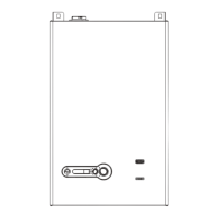
4.13 AC Electrical Power Wiring
External AC power is connected to the unit inside the electrical
box, located on the inside of the front doors. Open the front doors
and remove the panel mounted in the upper part of the left front
door of the unit as shown in Fig. 19.
Service
Display
Fig. 19
Front Door Internal Layout
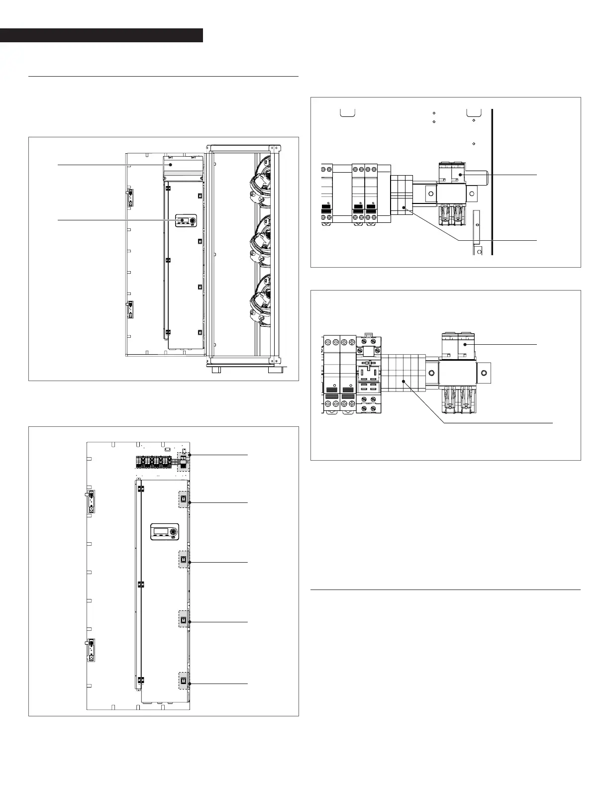
Loosen the screws of the Electrical box cover and remove panel to
access the internal connections shown in Fig. 20.
Front Door
Electrical box
Module Power
Switch
Module Power
Switch
Module Power
Switch
Module Power
Switch
Fig. 20
Front Door Electrical box
7All of the components in the Electrical box are mounted on a DIN
rail.
Main Switch
(backside view)
Terminal Blocks
Fig. 21
AR 1000, AR 1500 Front Door Electrical components
Fig. 22
Main Switch
(backside view)
Terminal Blocks
AR 2000 Front Door Electrical components
9
WARNING: The main switch shown in Fig. 22 and Fig. 23 does
not remove power from the left door terminal blocks.
NOTE: All electrical conduit and hardware must be installed so that
it does not interfere with the removal of any unit covers, inhibit
service/maintenance, or prevent access between the unit and
walls or another unit.
4.13.1 Electrical Power Requirements
The voltage conguration of Array AR 1000, AR 1500 and AR 2000 is
as follows:
− AR 1000, AR 1500: 120VAC/1PH/60Hz
− AR 2000: 230V/1Ph/60Hz
Each unit must be connected to a dedicated electrical circuit.
NO OTHER DEVICES SHOULD BE ON THE SAME ELECTRICAL CIRCUIT AS
THE BOILER.