30
INSTALLATION
BOILER
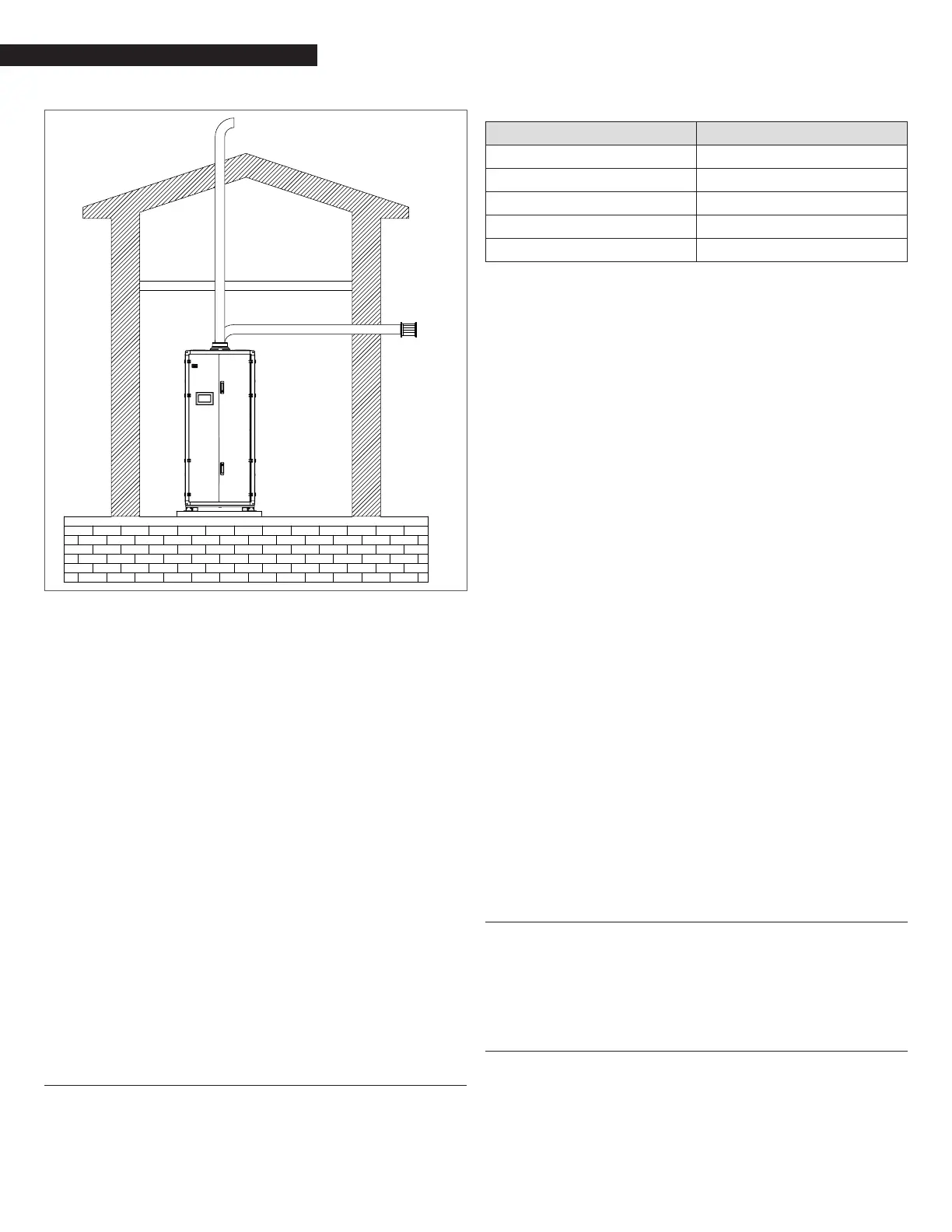
Fig. 40
Exhaust Located on Side Wall
− It is not recommended to terminate vent above any door or
window, as condensate can freeze causing ice formations.
− Do not use chimney as a raceway if another boiler or
replace is vented into or through chimney.
− Because the unit is capable of discharging low temperature
exhaust gases, the ue must be pitched back towards the
unit a minimum of 1/4” per foot to avoid any condensate
pooling and to allow for proper drainage.
− While there is a positive ue pressure during operation,
the combined pressure drop of vent and combustion air
systems must not exceed the limits listed in “Appendix I -
Venting Size Data”.
−
Fittings as well as pipe lengths must be calculated as part of the
equivalent length.
− For a natural draft installation the draft must not exceed -
0.25” w.c.
− These factors must be planned into the vent installation. If
the maximum allowable equivalent lengths of piping are
exceeded, the unit will not operate properly or reliably.
− For Massachusetts installations, contact companies able
to provide vent systems which conform to all applicable
requirements for installations within the Commonwealth
of Massachusetts.
− For installation of multiple boilers, common venting shall be
sized based on the data in “Appendix I - Venting Size Data”.
4.16 Combustion Air
Air supply is a direct requirement of ANSI 223.1, NFPA-54, CSA
B149.1 and local codes. These codes should be consulted before a
permanent design is determined.
Array boilers utilize combustion air from the space in which they
are installed, or utilize combustion air ducted directly to the unit.
Ventilation air must be provided in either case.
Material Standard
ABS ANSI/ASTM D1527
PVC Schedule 40 ANSI/ASTM D1785 or D2665
CPVC Schedule 40 ANSI/ASTM F441
Polypropylene ULC S636
Single wall galvanised steel 26 gauge
In cold climates it is essential to provide a motorized air inlet
damper to control the supply of combustion air and prevent
nuisance condensation.
The combustion air must be free of:
− Permanent wave solutions;
− Chlorinated waxes/cleaners;
− Chlorine-based swimming pool chemicals;
− Calcium chloride
− Sodium chloride used for water softening;
− Refrigerant leaks;
− Paint or varnish removers;
− Hydrochloric acid/muriatic acid;
− Cements and glues;
− Antistatic fabric softeners used in clothes dryers;
− Chlorine-type bleaches, detergents, and cleaning solvents
found in household laundry rooms;
− Adhesives used to fasten building products and other
similar products.
To prevent contamination do not connect the combustion air inlet
and exhaust near:
− Dry cleaning/laundry areas and establishments;
− Swimming pools;
− Metal fabrication plants;
− Beauty shops;
− Refrigeration repair shops;
− Photo processing plants;
− Auto body shops;
− Plastic manufacturing plants;
− Furniture renishing areas and establishments;
− Remodeling areas;
− Garages with workshops
Whenever the environment contains these types of chemicals,
combustion air MUST be supplied from a clean area outdoors for the
protection and longevity of the equipment and warranty validation.
The more common methods of combustion air supply are outlined
in the following sections.
4.16.1 Combustion Air From Outside the Building
Air supplied from outside the building must be provided through two
permanent openings. For each unit these two openings must have
a free area in accordance with the requirements of CAN/CSA B149.1,
Natural Gas and Propane Installation Code. The free area must take
into account restrictions such as louvers and bird screens.
4.16.2 Combustion Air From Inside the Building
When combustion air is provided from within the building, it must
be supplied through two permanent openings in an interior wall.
Each opening must have a free area of not less than one square inch
per 1000 BTUH of total input or 3000 square inches of free area. The
free area must take into account any restrictions, such as louvers.