20
INSTALLATION
inlet block” will appear on the screen.
At this point press the Reset button. The error will turn off.
Module level:
A Low Water Cut Off (LWCO) sensor is installed on top of the supply
tting of each heat exchanger. To check its functionality, go to the
HMI touchscreen, access the Module screen (see section 6.3.4),
push MODULE TEST, then LWCO TEST button and conrm. The error
message “LWCO2 error” will appear on the screen.
At this point press the Reset button. The error will turn off.
4.9 High Limit Safety Switch
A high limit safety switch is installed on each heat exchanger of the
boiler. To simulate a high limit lockout at 203°F go to the relevant
Module screen, press ‘Module Test’, then ‘High Limit Test’ button
The control will display “MN: Max. Thermostat Lock Error”.
At this point press the reset button on the Module screen to restart
the module.
4.10 Pressure Relief Valve Installation
ASME rated Pressure Relief Valves are factory installed in each
Array Boiler. The standard pressure rating for the relief valves is
75 PSI. The relief valves are installed on each hot water horizontal
manifold of the boiler as shown in Fig. 12. The relief valves’ drain
piping must be connected to a nearby oor drain. In multiple unit
installations the discharge lines must not be manifolded together.
Each must be individually run to a suitable discharge location.
Relief valves should be manually operated at least once a year. If
a relief valve discharges periodically, this may be due to thermal
expansion in a closed water supply system.
Contact the water supplier or local plumbing inspector on how to
correct this situation.
Do not plug the relief valve.
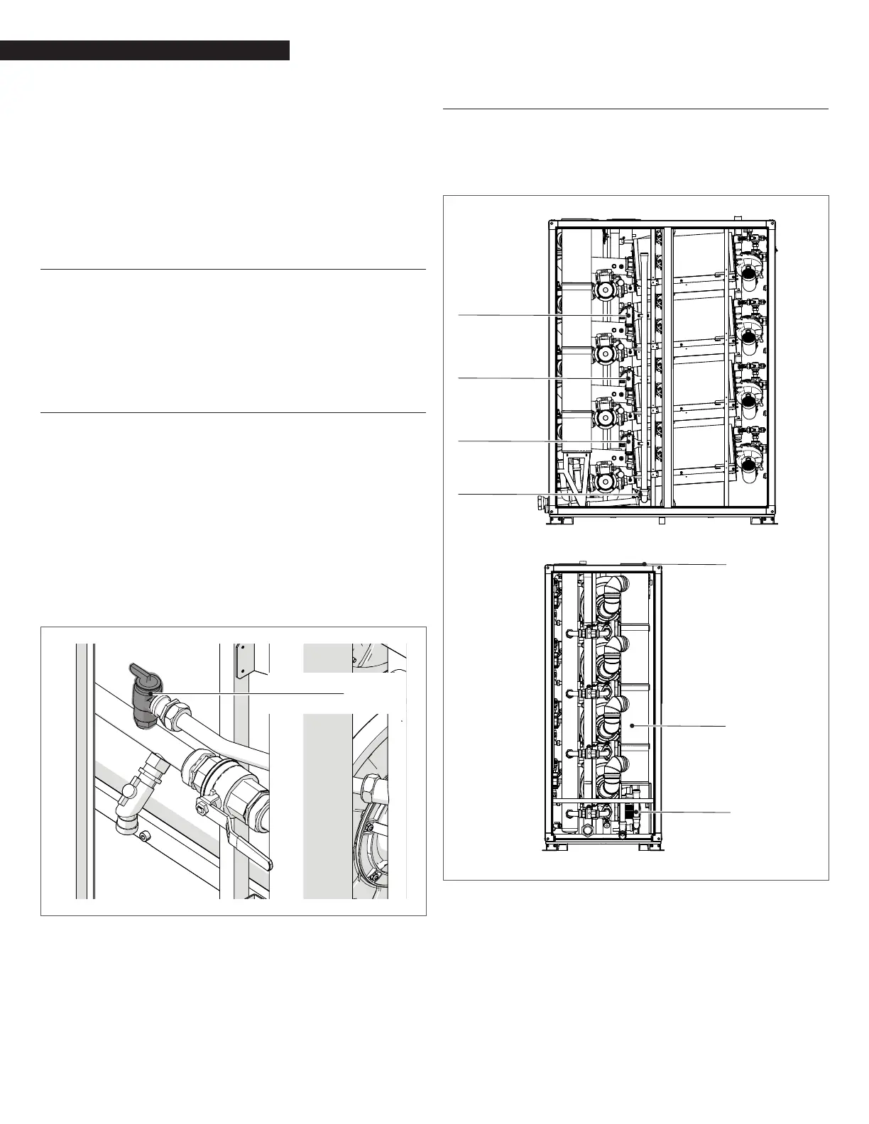
75PSI Relief valve
(one for each module)
Fig. 12
Pressure Relief Valve Location
4.11 Condensate Drain and Piping
The Array Boiler is designed to condense water vapor from the
ue products. Each heat exchanger of the boiler is equipped
with a condensate trap (see Fig. 13), while a syphon collects the
condensate of the vertical ue manifold.
Condensate
Trap
Condensate
Trap
Condensate
Trap
Condensate
Trap
Fill the syphon with
water from the top
of the vertical flue
manifold BEFORE
connecting
the vent piping
Vertical Flue
Manifold
Syphon
Fig. 13
Condensate Drain System