21
INSTALLATION
9
WARNING: At the Start-up and after prolonged shutdown of
the boiler, the condensate traps and the syphon must be lled
with water prior to restarting it, otherwise combustion gases
may enter the room with a risk of an excessive level of carbon
monoxide.
− The installation must have provisions for suitable drainage
or collection of the condensate exiting the boiler traps.
− The condensate water shall be discharged at atmospheric
pressure, by dripping into a suitable drain, and shall be
neutralized prior to draining per local/national codes.
− The condensate drain tube must pitch away from the boiler
(1/4” slope per foot) and must never reduce its diameter
downstream.
− Never use copper pipes or other material not intended
for the specic purpose, because the acidic nature of
the condensate will cause a rapid deterioration of the
unsuitable piping and/or exposed components.
− Check that the condensate drain pipe is adequately sloping
towards the discharge point avoiding high points, which can
inhibit the ow of the condensate. The condensate pipe must
be installed in such a way so as to avoid the freezing of any
liquid.
9
WARNING: Verify condensate disposal / neutralization is in
accordance with local, state and federal regulations.
If a oor drain is not available, a condensate pump can be used
to remove the condensate to an alternate drain. The maximum
condensate ow rate is 7.9 GPH for Array AR 1000, 13.9 GPH for Array
AR 1500 and 15.9 GPH for Array AR 2000. The drain line must be
removable for routine maintenance.
9
CAUTION: Use PVC, CPVC, stainless steel, aluminum or
polypropylene for condensate drain piping. DO NOT use carbon
steel or copper components.
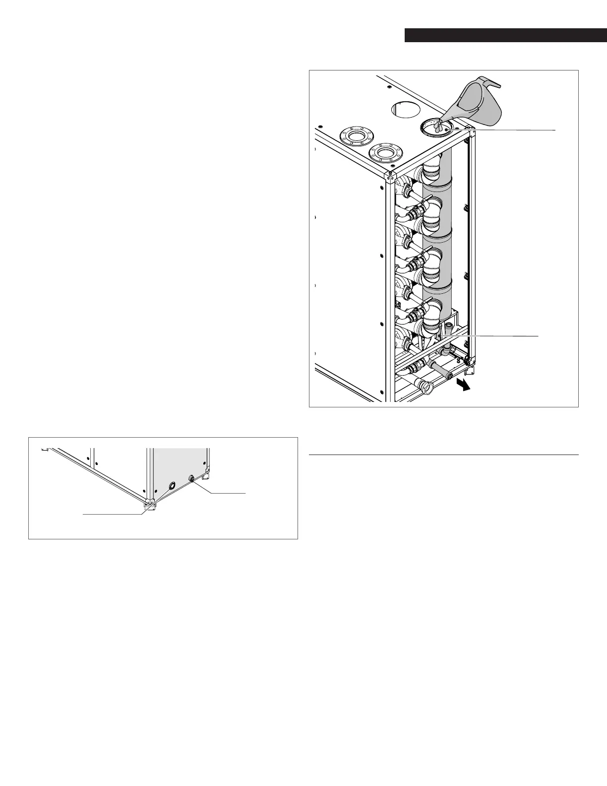
(1" PVC adapter
included)
Relief Valves Manifold
(2.5" NPT adapter included)
Fig. 14
Condensate Drain and Relief Valves Manifold Locations
The recommended procedure for lling the siphon at the bottom of
the vertical ue manifold before the start-up or after a prolonged
shutdown is described below:
− Before connecting the external exhaust venting to the
boiler, access the top panel, remove the protective cap from
the ue exit and pour water into it.
− Keep lling the siphon (at least 8 oz. of water are required)
until some water starts owing from the condensate drain
exit.
with water
Syphon
Fig. 15
Filling the siphon
4.12 Gas Supply Piping
Array AR 1000, AR 1500 and AR 2000 boilers contain a 1.5 inch NPT
gas inlet connection on the top of the unit as shown in Fig. 11.
9
WARNING: Never use matches, candles, ames or other sources
of ignition to check for gas leaks.
9
CAUTION: Many of the soaps used for gas pipe bubble-leak
testing are corrosive to metals. Therefore, piping must be
rinsed thoroughly with clean water after leak checks have
been completed.
NOTE: All gas piping must be arranged so that it does not interfere
with the removal of any covers, inhibit service and/or maintenance,
or restrict access between the unit and walls, or another unit.
− Prior to installation, all pipes should be de-burred and
internally cleared of any scale, metal chipss, oil, water or
other foreign particles. Do not install any exible connectors
or unapproved gas ttings. Piping must be supported only
from the oor, ceiling or walls, and must not be supported
by the unit.
− A suitable piping compound, approved for use with natural
gas, should be used. Any excess must be wiped off to
prevent clogging of components.
− To avoid unit damage when pressure testing gas piping,
isolate the unit from the gas supply piping. At no time
should the gas pressure applied to the unit exceed 13.5”
w.c. Leak test all external piping thoroughly using a soap
and water solution or suitable equivalent. The gas piping
used must meet all applicable codes.