49
SHUTDOWN
49
APPENDIX
APPENDIX
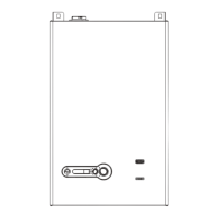
CONNECTION DIAGRAM 905PB DISPLAY
PBOX_3R
J7-02
J7-01
AL-BUS
RS485 / Mod BUS
L-BUS
J25-2
J25-1
J25-3
J25-5
J25-4
J25-6
B
GND
AL
A
AL
+24V
905PB05_3R
Connector Function
J7 PC interface
J25 Connection to MN control/Modbus
905PB05_3R Display: RJ-11 Connector:
1: GND/VSS
2: ModBus_B (= Data -)
3: ModBus_A (= Data +)
3: AL_Comm
5: VSS
6: +24V
To 905MN
1 2 3 4 5 6
J25 Wire Colors:
J25-1: Grey
J25-2: Black
J25-3: Green
J25-4: Yellow
J25-5: Red
J25-6: Blue
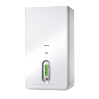
CONNECTION DIAGRAM 905PB DISPLAY
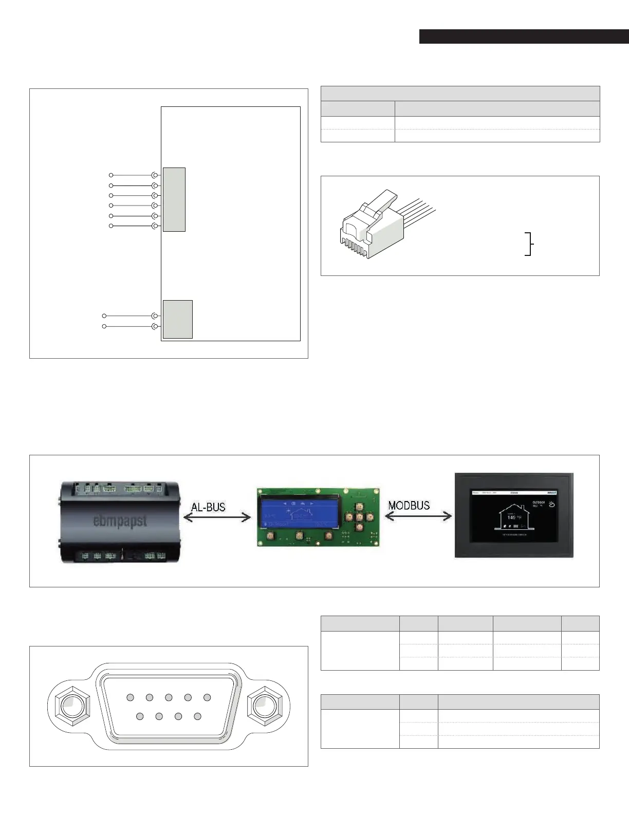
CONNECTION DIAGRAM 905TS (Touchscreen) AND 905PB DISPLAY
Modbus connection diagram between the 900PB and 900TS
Pins on connector COM1 of the 900TS:
6 7 8 9
1 2 3 4 5
Primary connection to 900PB:
Communication Pin Function Connect to
COM2
(Master)
5 GND 900 PB (J25-1)
7 RS 485 + 900 PB (J25-3)
8 RS 485 - 900 PB (J25-2)
Secondary connection to BMS (pre-wired):
Communication Pin Function
COM1
(Slave)
4 RS485 +
9 RS485 -
5 GND