82
ENGLISH
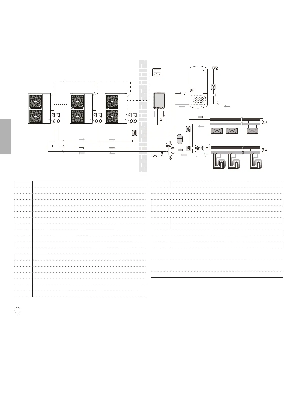
8.7 Application 7
The units are installed in parallel and can be used for cooling, heating and hot water.
6 units can be connected in parallel. Please refer to 9.7.5 for the parallel system electrical control system connection diagram.
The parallel system can control and view the operation of the entire system only by connecting the master to the wire controller.
If the DHW function is required, the water tank can only be connected to the master unit water circuit through a three-way valve, and
controlled by the master unit.
If you need to link with AHS, the AHS can only be connected to the master waterway and controlled by the master unit; The connection
and function of the terminal are the same as the single unit, please refer to the application 8.1~8.6.
2
1-1
1-2
1-n
3
8.1
25
10
4
67
8.2
8
9
19
23
23.1
23.2
18
----
FHL1 FHL2 ---- FHLn
----
FCU1 FCU2 ---- FCUn
24
11
11
17
16
16
AHS
12.1
12.2
12.3
12
13
14
15
16
16
2
3
16
2
3
Code Assembly unit
1-1 Outdoor unit: master
1-2...1-n Outdoor unit: slave
2 <VKDSH¿OWHU
3 6WRSYDOYH¿HOGVXSSO\
4 Wired controller
6 'UDLQYDOYH¿HOGVXSSO\
7 )LOOYDOYH¿HOGVXSSO\
8 %DODQFHWDQN¿HOGVXSSO\
8.1 Air purge valve
8.2 Drain valve
9 ([SDQVLRQYHVVHO¿HOGVXSSO\
10 PUMP_ORXWVLGHFLUFXODWLRQSXPS¿HOGVXSSO\
11 &ROOHFWRUGLVWULEXWRU¿HOGVXSSO\
12 Domestic hot water tank ¿HOGVXSSO\
12.1 Air purge valve
12.2 Heat exchanger coil
12.3 Booster heater
13 T5: DHW tank temp. sensor
14 Hot water tap¿HOGVXSSO\
15 PUMP_D: DHW pump¿HOGVXSSO\
16 One way valve¿HOGVXSSO\
17 Bypass valve ¿HOGVXSSO\
18 SV1: 3-way valve¿HOGVXSSO\
19 SV2: 3-way valve¿HOGVXSSO\
23 Mixing station ¿HOGVXSSO\
23.1 PUMP_C: zone 2 pump¿HOGVXSSO\
23.2 SV3: 3-way valve¿HOGVXSSO\
24 TW2: ]RQHZDWHUÀRZWHPSHUDWXUH (accessory)
25 Tbt1: Balance tank temp. sensor (accessory)
FHL
1… n
)ORRUKHDWLQJORRS¿HOGVXSSO\
FCU
1… n
)DQFRLOXQLWV¿HOGVXSSO\
AHS $GGLWLRQDOKHDWLQJVRXUFHERLOHU¿HOGVXSSO\
NOTE
The volume of balance tank (8) should be greater than 40*n ("n" means n ° units installed, max 6 units). The drain valve (6) should be
installed at the lowest positon of the system.
The water inlet and outlet pipe joints of each unit of the parallel system should be connected with soft connections, and one-way valves
must be installed at the water outlet pipe.
The Tbt1 temperature sensor must be installed in the parallel system (otherwise unit cannot be started), the temperature point is set
in the balance tank (8).