84
ENGLISH
Code Assembly unit Explanation
1 Air purge valve Remaining air in the water circuit will be automatically re-moves air from the water circuit
2 Expansion vessel Balances water system pressure (expansion vessel volume: 8l)
3 Circulation pump Circulates water in the water circuit
4 Pressure relief valve
Prevents excessive water pressure by opening at 3 bar and discharging water from the water
circuit
5 Manometer Provides water circuit pressure readout
6
Flow switch
'HWHFWVZDWHUÀRZUDWHWRSURWHFWFRPSUHVVRUDQGZDWHUSXPSLQWKHHYHQWRILQVXႈFLHQWZDWHU
ÀRZ
7 Refrigerant gas connection
8 Refrigerant liquid connection
9 Plate heat exchanger Transfer heat from the refrigerant to the water
10 Water outlet connection
11 Water inlet connection
12.1 Electrical heating tape For heating plate heat exchanger
12.2 Electrical heating tape For heating connection pipe of expansion vessel
Temperature sensors
Four temperature sensors determine the water and refrigerant temperature at various points
in the water circuit.(T2B; T2; Tw_out; Tw_in)
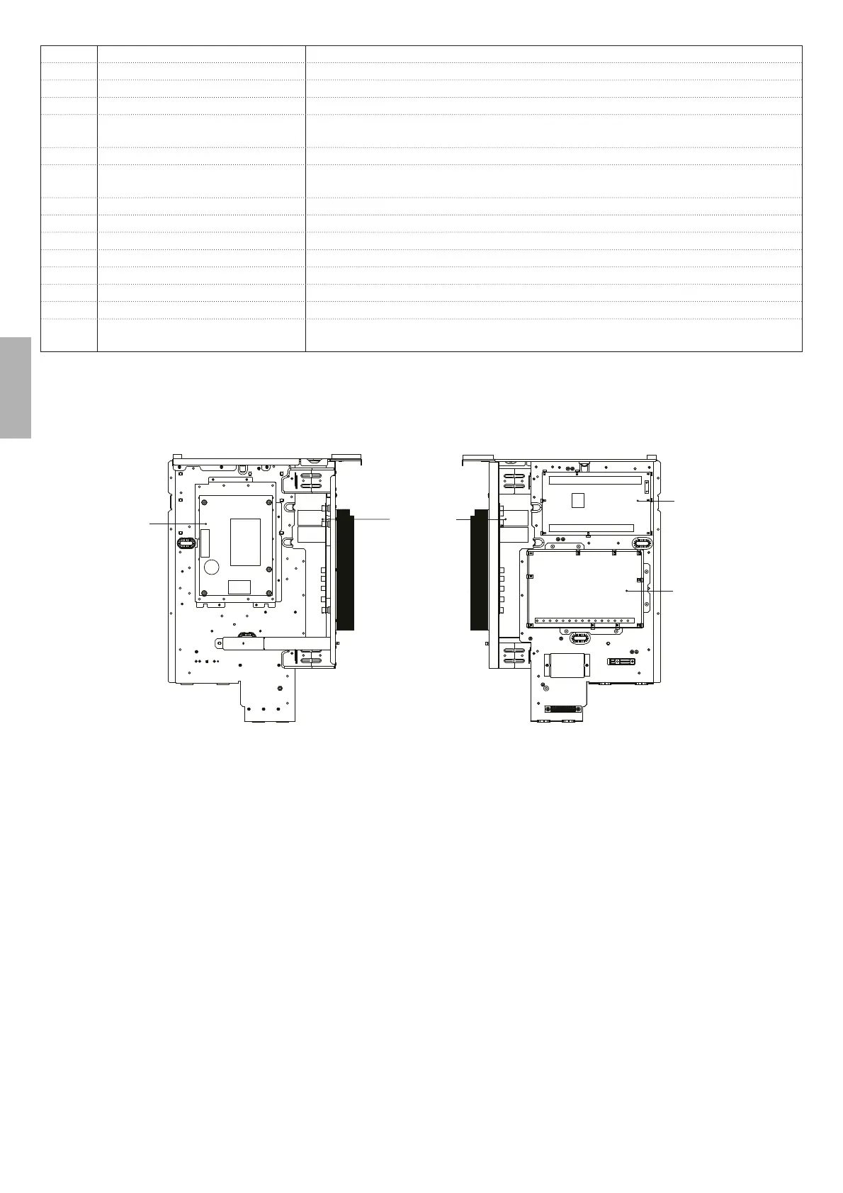
9.3 Electronic control box
Note:The picture is for reference only, please refer to the actual product.
Note:The picture is for reference only, please refer to the actual product.
Inverter module
(PCB A)
Main control
board of unit
(PCB B)
Main control
board of
hydraulic module
Filter board
(PCB C)
Back view Front view