100
ENGLISH
a. For room thermostat (Low voltage): see 9.7.6 2) for room thermostat
b. For smart grid:
The unit has smart grid function, there are two ports on PCB to connect SG signal and EVU signal as following:
1. When EVU signal is on , and SG signal is on, as long as the DHW mode is set to be valid, heat pump will operate DHW mode priority and the
'+:PRGHVHWWLQJWHPSHUDWXUHZLOOEHFKDQJHWR&7&WKH7%+LVRQ7&WKH7%+LVRႇ
:KHQ(98VLJQDOLVRQDQG6*VLJQDOLVRႇDVORQJDVWKH'+:PRGHLVVHWWREHYDOLGDQGWKHPRGHLVRQKHDWSXPSZLOORSHUDWH'+:
PRGHSULRULW\776WKH7%+LVRQ776WKH7%+LVRႇ
:KHQ(98VLJQDOLVRႇDQG6*VLJQDOLVRQWKHXQLWRSHUDWHVQRUPDOO\
:KHQ(98VLJQDOLVRႇDQG6*VLJQDOLVRႇWKHXQLWRSHUDWHVDVEHORZ7KHXQLWZLOOQRWRSHUDWH'+:PRGHDQGWKH7%+LVLQYDOLGGLVLQIHFW
IXQFWLRQLVLQYDOLG7KHPD[UXQQLQJWLPHIRUFRROLQJKHDWLQJLV´6*5811,1*7,0(´WKHQXQLWZLOOEHRႇ
10 START-UP AND CONFIGURATION
7KHXQLWVKRXOGEHFRQ¿JXUHGby the installer to match the installation environment (outdoor climate, installed options, etc.) and user expertise.
b
CAUTION
It is important that all information in thiVFKDSWHULVUHDGVHTXHQWLDOO\E\WKHLQVWDOOHUDQGWKDWWKHV\VWHPLVFRQ¿JXUHGDVDSSOLFDEOH
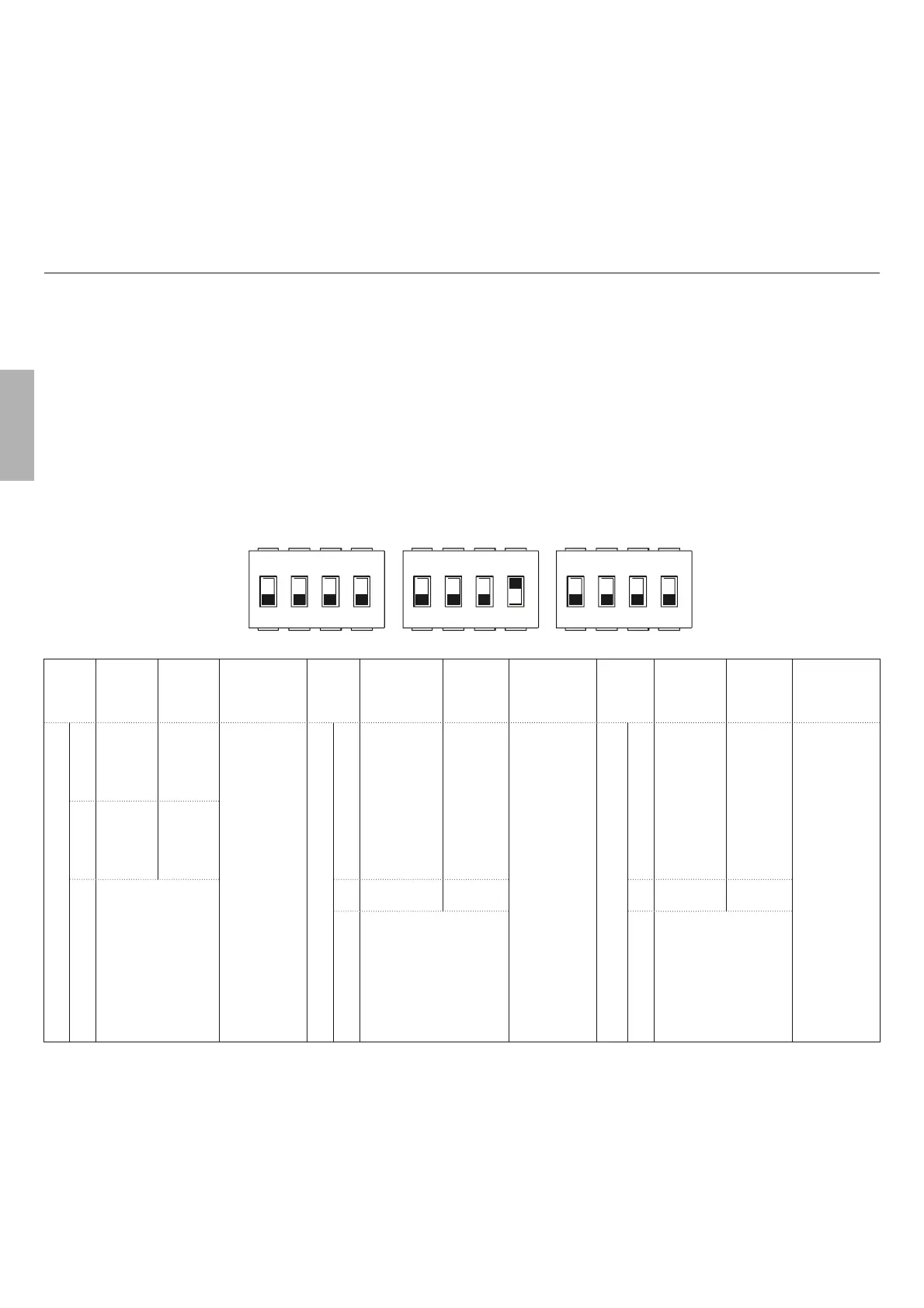
10.1 DIP switch settings overview
10.1.1 Function setting
',3VZLWFKLVORFDWHGRQWKHK\GUDXOLFPRGXOHPDLQFRQWUROERDUGVHH0DLQFRQWUROERDUGRIK\GUDXOLFPRGXOHDQGDOORZVFRQ¿JXUDWLRQ
of additional heating source thermistor installation, the second inner backup heater installation, etc.
b
WARNING
6ZLWFKRႇWKHSRZHUVXSSO\EHIRUHRSHQLQJWKHVZLWFKER[VHUYLFHSDQHODQGPDNLQJDQ\FKDQJHVWRWKH',3VZLWFKVHWWLQJV
Operate the switches with an insulated stick (such as a closed ball-point pen) to avoid electrostaric damage to the components.
1 2 3 4 12 3
S1
4
S2
ONOFF
12 3
S4
4
DIP
switch
ON= 1 OFF=0 Factory Defaults
DIP
switch
ON= 1 OFF=0 Factory Defaults
DIP
switch
ON= 1 OFF=0 Factory Defaults
S1
1 Reserved Reserved
Refer to eletri-
cally controlled
wiring diagram
S2
1
Start pump_o
after 24 hours
will be invalid
Start pump
after 24
hours will
be valid
Refer to eletri-
cally controlled
wiring diagram
S4
1
Master unit:
clear addres-
ses of all sla-
ve units
Slave unit:
clear its own
address
Keep the
current
address
Refer to eletri-
cally controlled
wiring diagram
2 Reserved Reserved
3/4
0/0 = without BH and
AHS
1/0 = with IBH
0/1 = with AHS for heat
mode
1/1 = with AHS for heat
mode and DHW mode
2 without TBH
with TBH
2 Reserved Reserved
3/4
0/0=variable speed pump,
Max head: 8.5m
0/1=constant speed pump
1/0=variable speed pump,
Max head: 10.5m
1/1=variable speed pump,
Max head: 9.0m
3/4 Reserved
10.2 Initial start-up at low outdoor ambient temperature
During initial start-up and when water temperature is low, it is important that the water is heated gradually. Failure to do so may result in concrete
ÀRRUVFUDFNLQJGXHWRUDSLGWHPSHUDWXUHFKDQJH3OHDVHFRQWDFWWKHUHVSRQVLEOHFDVWFRQFUHWHEXLOGLQJFRQWUDFWRUIRUIXUWKHUGHWDLOV
7RGRVRWKHORZHVWZDWHUÀRZVHWWHPSHUDWXUHFDQEHGHFUHDVHGWRDYDOYHEHWZHHQ&DQG&E\DGMXVWLQJWKH)256(59,&(0$1
Refer to 10.5.12 "SPECIAL FUNCTION" .
10.3 Pre-operation checks
Checks before initial start-up.
b
DANGER
6ZLWFKRႇWKHSRZHUVXSSO\EHIRUHPDNLQJDQ\FRQQHFWLRQV