99
ENGLISH
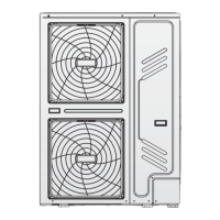
9. For additional heat source control
AHS1 AHS2
27 28
ADDITIONAL HEAT SOURCE
CONTROL SIGNAL OUTPUT
Voltage 220-240VAC
Maximum running current (A) 0,2
Wiring size (mm²) 0,75
Control port signal type Type 2
10. For defrosting signal output
DEFROSTING
PROMPT SIGNAL
FUSE
31
DFT2 DFT2
32
NL
Voltage 220-240VAC
Maximum running current (A) 0,2
Wiring size (mm²) 0,75
Control port signal type Type 1
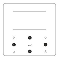
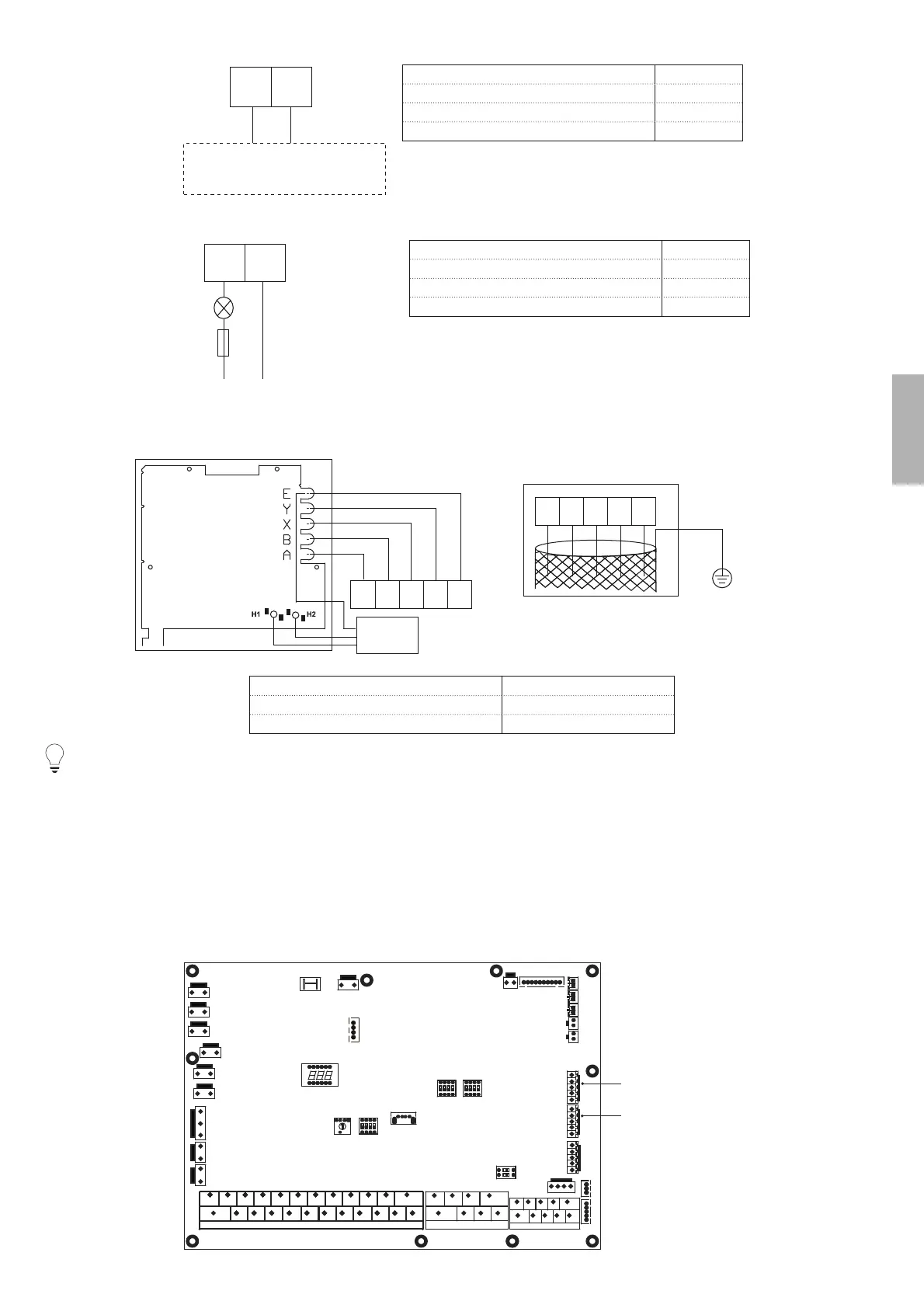
11. For wired controller
EABXY
12345
XT6
“PLEASE USE SHIELDED WIRE AND
EARTH THE WIRE.”
COMMUNICATION
ABXYE
12345
MODBUS
E
A+
B-
Wire type 5 wire shielded cable
Wire section (mm
2
) 0,75~1,25
Maximum wire length (m) 50
NOTA
This equipment supports MODBUS RTU communication protocol:
As described above, during wiring, port A in the unit terminal XT6 corresponds to port A in the user interface. Port B corresponds to port B. Port
X corresponds to port X. Port Y corresponds to port Y, and port E corresponds to port E.
Procedure
Remove the rear part of the user interface.
Connect the cable to the appropriate terminals as shown in the picture.
Reattach the rear part of the user interface.
12. For other functional ports
For room thermostat
(Low voltage)
For smart grid
3029
32
25 26 27 28
31
7
1211
109
18
8
7
5
2322 24
12
13
3
4
6
2014 15 17 1916 21
689
10
5
4321
CN4
CN22
CN5
S3
DIS1
CN24
CN1
CN2
CN6
CN8
CN13
CN15
CN16
CN18
CN28
S2
CN42
CN21
S1
S4
CN11 CN7
CN17
CN14
CN19
CN30
CN35
CN31
CN36
CN25
CN29
CN40
CN41
CN32
SW9