126
ENGLISH
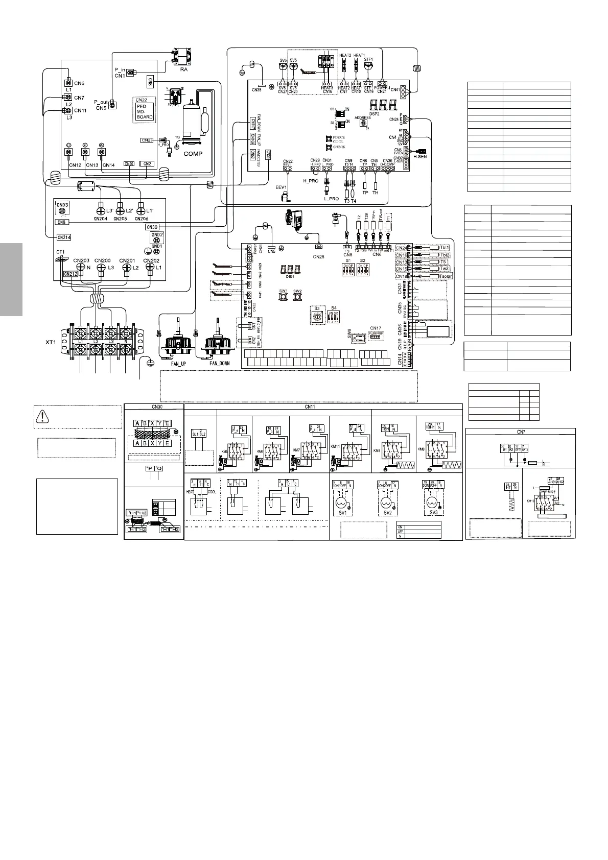
Electrical diagram
......
SW9
XT3
OFF
ON
Temperature
controller
HEAT 8
HEAT 7 HEAT 6 HEAT 5
IBH0
CN32
1
SL1
2
SL2
3
H
4
C
5
1ON
6
1OFF
7
2ON
8
2OFF
9
P_c
10
P_o
11
P_s
12
P_d
13
TBH
14
IBH1
15
L1
16
N
17
N
18
N
19
3ON
20
3OFF
21
N
24
N
23
N
22
N
29
N
25
HT
26
R2
27
AHS1
28
AHS2
30
R1
31
DFT2
32
DFT1
6
P
7
Q
8
E
9
H1
10
H2
1
A
2
B
3
X
4
Y
5
E
CN11
CN7
CN30
Leakage protection Switch must
be installed to the Power Supply
of the unit.
After power off, it will take 5
minutes to power on.
The wiring picture shown
is for reference only,
actual product may vary.
POWER SUPPLY
380-415V 3N~
BLACK GRAY
BROWN
BLUE
FERRITE CORE
GRAY
FERRITE CORE
FERRITE CORE
FERRITE CORE
FERRITE CORE
FERRITE CORE
FERRITE CORE
FERRITE CORE
BLACKGRAY
BROWN
BLUE
BLACK BLACK BLACK
RED BLACK BLUE
NERO
NERO
NERO
RED
RED
RED
RED
BLACK
RED
BLUE
To the heating tape
of drainage outlet
(<200mA)
MAIN CONTROL BOARD
RED
BLACK
WHITE
PUMP
FLOWSWITCH
BLUE
PUMP
HYDRO-BOX CONTROL BOARD
ROOM
THERMOSTAT
(LOW VOLTAGE)
SMART GRID
(LOW VOLTAGE)
- Equipment must be grounded.
- All high-voltage external load, if it is metal or a grounded port, must be grounded.
- All external load current is needed less than 0,2 A; if the single load current is greater than 0,2A, the load must be controlled through AC contctor.
- “AHS1”, “AHS2”, “A1”, “A2”, “R1”, “R2” and “DFT1”, “DFT2” wiring terminal ports provide only the switch signal.
- Expansion valve E-Heating tape, Plate heat exchanger E-Heating tape and Flow switch E-Heating tape share a control port.
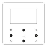
WIRE CONTROLLER
CONNECT TO WIRE CONTROLLER
COMMUNICATION
RESERVED
Master unit
Slave unit 1
Slave unit x
System parallel
Slave unit
Master unit
SOLAR PUMP
(The current of load is 0,2 A, the AC contactor is required to be connected for the load)
(
The current of load is 0,2 A, the AC contactor is required to be
connected for the load
)
TBH/IBH1
SOLAR SIGNAL
INPUT
CONNECT TO SOLAR
PUMP STATION
220~240VAC INPUT
POWER SUPPLY
SOLAR PUMP
POWER SUPPLY
POWER SUPPLY
POWER SUPPLY
POWER SUPPLY
POWER SUPPLY
OUTSIDE CIRCULATOR
PUMP OR ZONE 1 PUMP
ZONE 2 PUMP DHW PIPE PUMP
TBH IBH1
A1
A2
A1
A2
A1
A2
A1
A2
A1
A2
A1
A2
Method 1:
Method 2:
ALIMENTAZ.
ALIMENTAZ.
ROOM THERMOSTAT (HIGH VOLTAGE)
ALIMENTAZ.
ALIMENTAZ.
Method 3:
RT
RT
RT
RT
External ON/OFF thermostat
1 Power supply of machine and room thermostat must be connected to the same Neutrla Line and Live Line
2 For more information, please refer to Installation & Operation manual
TERMINAL MAX LOAD OUTPUT:
0,5A (IN RUSH) ~ 250VAC
0,2A (CONTINUED) ~ 250VAC
DESCRIPTION
NORMAL OPEN TERMINAL
NORMAL CLOSE TERMINAL
NEUTRAL TERMINAL
NOTE
VALVE
FUSE
PASSIVE SWITCH OUTPUT
RUN
DEFROST
FUSE
ADDITIONAL HEAT SOURCE
ANTIFREEZE
E-HEATING TAPE
NOTE
NOTE
The current of load is 0,2 A,
the contactor is required to be
connected for the load
additional heat source
TERMINAL MAX LOAD OUTPUT:
0,5A (IN RUSH) ~ 250VAC
0,2A (CONTINUED) ~ 250VAC
FILTER BOARD
INVERTER COMPRESSOR
DRIVER BOARD
heat belt 8
heat belt 7
heat belt 6
heat belt 5
CODE NAME
Inverter compressor
Electric expansion valve
Solenoid valve
4-way valve
AC current transformer
Big 4-phase terminal
High pressure sensor
High/Low pressure switch
Crankcase heating
DC fan motor
Reactor
Piping temperature sensor
Outdoor ambient temperature sensor
Compressor exhaust temperature sensor
Compressor return temperature sensor
COMP
EEV1/2
SV5/SV6
STF1/STF2
CT1
XT1
H-SEN
H_PRO/L_PRO
HEAT1/HEAT2
FAN_UP/DOWN
RA
T3/T3A
T4
TP
TH
Additional heat source
Domestic hot water
Remote switch
Solar pump
DHW pipe pump (field supply)
Zone 2 pump (field supply)
Internal circulator pump
Motorized 3-way valve (field supply)
AC contactor
Heat mode/Cool mode (thermostat)
Outside circulator pump (field supply) or
Zone 1 pump (field supply)
Flowswitch
Solar energy
Commercial power
Temperature sensor
AHS
DHW
M1/M2
P_s
P_d
P_c
PUMP
SV1-3
KM5-KM11
HT/CL
P_o
FS
SG
EVU
T2, TB2, TW_in,
TW_out, T1,
Tbt1, Tbt2, T5,
Tw2, Tsolar
Temp. sensor code Property values
T2/TB2
T1/TW_out
TW_in/ T5/T1B
B
25/50
=4100K, R
25°C
=10k
B
0/100
=3970K, R
50°C
=17.6k
Operating behavior
Increased operation output
CN35 - SMART GRID
EVU SG
Normal operation
Decreased operation output
ON ON
ON OFF
OFF ON
OFF OFF