94
ENGLISH
NOTE
Please use H07RN-F for the power wire, all the cable are connect to high voltage except for thermistor cable and cable for user interface.
Equipment must be grounded.
All high-voltage external load, if it is metal or a grounded port, must be grounded.
All external load current is needed less than 0.2A, if the single load current is greater than 0.2A, the load must be controlled through
AC contactor.
"AHS1" "AHS2", "A1" "A2", "R1" "R2" and "DFT1" "DFT2" wiring terminal ports provide only the switch signal. Please refer to image of
9.7.6 to get the ports position in the unit.
Expansion valve E-Heating tape, Plate heat exchanger E-Heating tape and Flow switch E-Heating tape share a control port.
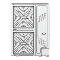
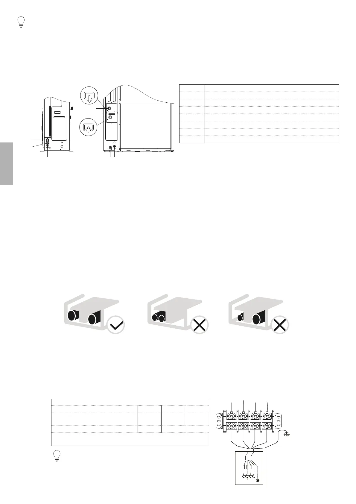
Code Assembly unit
1 High voltage wire hole
2 Low voltage wire hole
3 High voltage or low voltage wire hole
4 Water outlet
5 Water inlet
6 Drain outlet
7 Drainage pipe hole (for safety valve)
67
1
3
2
4
5
Field wiring guidelines
0RVW¿HOGZLULQJRQWKHXQLWLVWREHPDGHRQWKHWHUPLQDOEORFNLQVLGHWKHVZLWFKER[7RJDLQDFFHVVWRWKHWHUPLQDOEORFNUHPRYH
the switch box service panel.
b
WARNING
6ZLWFKRႇDOOSRZHULQFOXGLQJWKHXQLWSRZHUVXSSO\DQGEDFNXSKHDWHUDQGGRPHVWLFKRWZDWHUWDQNSRZHUVXSSO\LIDSSOLFDEOHEHIRUHUHPRYLQJ
the switch box service panel.
Fix all cables using cable ties.
A dedicated power circuit is required for the backup heater.
,QVWDOODWLRQVHTXLSSHGZLWKDGRPHVWLFKRWZDWHUWDQN¿HOGVXSSO\UHTXLUHDGHGLFDWHGSRZHUFLUFXLWIRUWKHERRVWHUKHDWHU3OHDVH
refer to the domestic hot water tank Installation & Owner's Manual. Secure the wiring in the order shown below.
Lay out the electrical wiring so that the front cover does not rise up when doing wiring work and attach the front cover securely.
Follow the electric wiring diagram for electrical wiring works (the electric wiring diagrams are located on the rear side of door).
,QVWDOOWKHZLUHVDQG¿[WKHFRYHU¿UPO\VRWKDWWKHFRYHUPD\EH¿WLQSURSHUO\
9.7.3 Precautions on wiring of power supply
Use a round crimp-style terminal for connection to the power supply terminal board. In case it cannot be used due to unavoidable reasons, be
sure to observe the following instructions.
'RQRWFRQQHFWGLႇHUHQWJDXJHZLUHVWRWKHVDPHSRZHUVXSSO\WHUPLQDO/RRVHFRQQHFWLRQVPD\FDXVHRYHUKHDWLQJ
:KHQFRQQHFWLQJZLUHVRIWKHVDPHJDXJHFRQQHFWWKHPDFFRUGLQJWRWKH¿JXUHEHORZ
Use the correct screwdriver to tighten the terminal screws. Small screwdrivers can damage the screw head and prevent appropriate
tightening.
Over-tightening the terminal screws can damage the screws.
Attach a ground fault circuit interrupter and fuse to the power supply line.
,QZLULQJPDNHFHUWDLQWKDWSUHVFULEHGZLUHVDUHXVHGFDUU\RXWFRPSOHWHFRQQHFWLRQVDQG¿[WKHZLUHVVRWKDWRXWVLGHIRUFHFDQQRW
DႇHFWWKHWHUPLQDOV
9.7.4 6SHFL¿FDWLRQVRIVWDQGDUGZLULQJFRPSRQHQWV
Door 1: compressor compartment and electrical parts: XT1.
NOTE
The ground fault circuit interrupter must be a high-speed type breaker
of 30 mA (<0,1 s).
POWER SUPPLY
380VAC~3N
FUSE
LPS
L1
L2
L3
N
1L1L2L2L3L3LN
KCALBKCALB
EULBEULBYARGYARG
NWORBNWORB
OUTDOOR UNIT POWER SUPPLY
Unit 18 kW 22 kW 26 kW 30 kW
Maximum overcurrent
protector (MOP)
18 21 24 28
Wiring size (mm²) 6666
Stated values are maximum values (see electrical data for exact
values)