97
ENGLISH
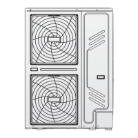
Room thermostat type2 (RT2) (Low voltage): “POWER IN” provide the working voltage to the RT.
3-phase
POWER SUPPLY
RT
N
HEAT
COOL
H
3
C
4
L1
TO CONTROL PCB
1L1L2L2L3L3LNN
There are three methods for connecting the thermostat cable (as described in the picture above) and it depends on the application.
Method A
RT can control heating and cooling individually, like the controller for 4-pipe FCU. When the hydraulic module is connected with the external
temperature controller, user interface FOR SERVICEMAN set THERMOSTAT and ROOM MODE SETTING to YES:
A.1 When unit detect voltage is 230VAC between C and N, the unit operates in the cooling mode.
A.2 When unit detect voltage is 230VAC between H and N, the unit operates in the heating mode.
A.3 When unit detect voltage is 0VAC for both side (C-N, H-N) the unit stop working for space heating or cooling.
A.4 When unit detect voltage is 230VAC for both side (C-N, H-N) the unit working in cooling mode.
Method B
RT provide the switch signal to unit. user interface FOR SERVICEMAN set ROOM THERMOSTAT to ONE ZONE:
B.1 When unit detect voltage is 230VAC between H and N, unit turns on.
B.2 When unit detect voltage is 0VAC between H and N, unit turns on.
NOTE
When ROOM THERMOSTAT is set to YES, the indoor temperature sensor Ta can’t be set to valid, unit running only according to T1.
Method C
Hydraulic module is connected with two external temperature controllers, while user interface FOR SERVICEMAN set ROOM THERMOSTAT to
DOUBLE ZONE:
C.1
When unit detect voltage is
230VAC
between
H and N,
zone1 turns on
.
When unit detect voltage is
0VAC
between
H and N,
]RQHWXUQVRႇ
C.2
When unit detect voltage is
230VAC
between
C and N,
zone2 turns on according to climate temp curve
.
When unit detect voltage is
0V
between
C and N,
]RQHWXUQVRႇ
.
C.3
When
H-N and C-N
are detected as
0VAC,
XQLWWXUQVRႇ
.
C.4
When
H-N1 and C-N
are detected as
230VAC,
both zone1 and zone2 turn on
.
NOTE
The wiring of the thermostat should correspond to the settings of the user interface (see "10.5.6 Room thermostat").
Power supply of machine and room thermostat must be connected to the same Neutral Line and (L2) Phase Line (for 3-phase unit
only).
Procedure
Connect the cable to the appropriate terminals as shown in the picture.
Fix the cable with cable ties to the cable tie mountings to ensure stress relief.
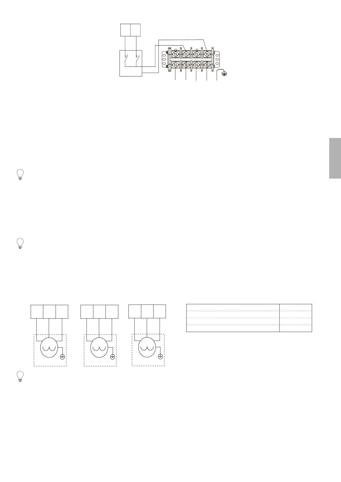
3. For 3-way value SV3
SV1
1ON
5
1OFF
6
N
16
SV2
2ON
7
2OFF
8
N
17
SV3
3ON
19
3OFF
20
N
18
Voltage 220-240VAC
Maximum running current (A) 0,2
Wiring size (mm²) 0,75
Control port signal type Type 1
NOTE
:LULQJRIWKHZD\YDOYHLVGLႇHUHQWIRU1&QRUPDOFORVHDQG12QRUPDORSHQ%HIRUHZLULQJUHDGWKH,QVWDOODWLRQ2ZQHUVPDQXDOIRUWKH
3-way valve carefully and install the valve as showed in the picture. Make sure to connect it to the correct terminal numbers.
Procedure
Connect the cable to the appropriate terminals as shown in the picture.
Fix the cable reliably.