89
ENGLISH
Before continuing installation of the unit, check the following:
WKHSUHVHQFHRID<¿OWHURQWKHZDWHULQOHWRIWKHKHDWSXPS
WKHPD[LPXPZDWHUSUHVVXUHEDU
WKHPD[LPXPZDWHUWHPSHUDWXUH&DFFRUGLQJWRVDIHW\GHYLFHVHWWLQJ
always use materials that are compatible with the water used in the system and with the materials used in the unit
HQVXUHWKDWFRPSRQHQWVLQVWDOOHGLQWKH¿HOGSLSLQJFDQZLWKVWDQGWKHZDWHUSUHVVXUHDQGWHPSHUDWXUH
drain taps must be provided at all low points of the system to permit complete drainage of the circuit during maintenance
air vents must be provided at all high points of the system. The vents should be located at points that are easily accessible for service.
An automatic air purge valve is provided inside the unit. Check that this air purge valve is not tightened so that automatic release of
air in the water circuit is possible.
9.4.2 Water volume and expansion vessel pre-pressure checks
The units are equipped with an expansion vessel of 8l that has a default pre-pressure of 1.0 bar. To assure proper operation of the unit, the
pre-pressure of the expansion vessel might need to be adjusted.
1) Check that the total water volume in the installation, excluding the internal water volume of the unit, is at least 40l. See 14 "Technical
VSHFL¿FDWLRQVWR¿QGWKHWRWDOLQWHUQDOZDWHUYROXPHRIWKHXQLW
NOTE
In most applications this minimum water volume will be satisfactory.
In critical processes or in rooms with a high heat load though, extra water might be required.
When circulation in each space heating loop is controlled by remotely controlled valves, it is important that this minimum water volume
is kept even if all the valves are closed.
2) Using the table below, determine if the expansion vessel pre- pressure requires adjustment.
3) Using the table and instructions below, determine if the total water volume in the installation is below the maximum allowed water volume.
Installation height
GLႇHUHQFH
:DWHUYROXPHO Water volume >230l
P No pre-pressuread justment required.
Actions required:
Pre-pressure must be increased, calculate according
to “Calculating the pre-pressure of the expansion
vessel" below.
Check if the water volume is lower than maximum
allowed water volume (use graph below).
>7 m
Actions required:
Pre-pressure must be increased, calculate according
to “Calculating the pre-pressure of the expansion
vessel" below.
Check if the water volume is lower than maximum
allowed water volume (use graph below).
Vaso di espansione dell'unità troppo piccolo per l'impianto.
+HLJKWGLႇHUHQFHLVEHWZHHQWKHKLJKHVWSRLQWRIWKHZDWHUFLUFXLWDQGWKHRXWGRRUXQLWVH[SDQVLRQWDQN8QOHVVWKHXQLWLVORFDWHGDWWKHKL-
JKHVWSRLQWRIWKHV\VWHPLQZKLFKFDVHWKHLQVWDOODWLRQKHLJKWGLႇHUHQFHLVFRQVLGHUHGWREH]HUR
Calculating the pre-pressure of the expansion vessel
7KHSUHSUHVVXUH3JWREHVHWGHSHQGVRQWKHPD[LPXPLQVWDOODWLRQKHLJKWGLႇHUHQFH+DQGLVFDOFXODWHGDVIROORZV3JEDU +P
bar.
Checking the maximum allowed water volume
To determine the maximum allowed water volume in the entire circuit, proceed as follows:
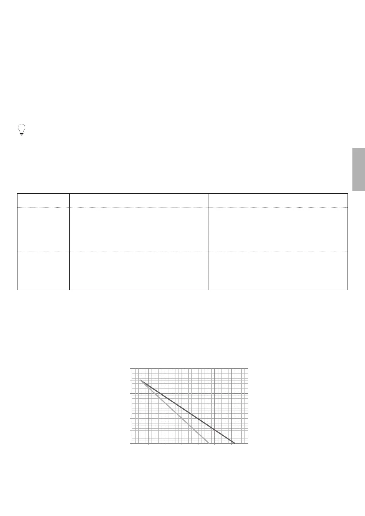
Determine the calculated pre-pressure (Pg) for the corresponding maximum water volume using the graph below.
Check that the total water volume in the entire water circuit is lower than this value. If this is not the case, the expansion vessel inside
the unit is too small for the installation.
0.3
0.8
1.3
1.8
2.3
2.8
0
3.3
50 100 150 200 250 300 350
A1
A2
Max. water volume (l)
Pre-pressure (bar)
Pre-pressione = pre-pressure of the expansion vessel
Maximum water volume = maximum water volume in the system
A1 System without glycol
A2 System without 25% propylene glycol