2862
8
GB
4. WORKING
4.1 COMBUSTION ADJUSTMENT
In conformity with Efficiency Directive EEC/92/42, the installation of the burner to the heat generator, setting
and testing must all be performed in respect of the instruction manual for the heater, including the controls
on the concentration of CO and CO
2
in the flue gases, the flue gas temperature and the average water and
air temperatures in the generator.
To suit the required appliance output, choose the proper nozzle and adjust the pump pressure, the setting
of the combustion head, and the air damper opening in accordance with the following schedule.
The values given in the table refer to a CEN boiler (in accordance with EN 267). They refer to 12.5% of
CO
2
, at sea level, room temperature and light oil temperature at 20°C, 50 Hz power frequency and com-
bustion chamber counterpressure at 0.
The values given in the table are just an indica-
tion; to get the best performance from the
burner, the regulations should be made on the
basis of the effective requirements of the gen-
erator.
With 60Hz power frequency, the burner must
be re-set, closing the air damper, so that the
amount of intake air is reduced.
4.2 RECOMMENDED NOZZLES
Delavan type W - B ; Danfoss type S - B
Monarch type R ; Steinen type S - Q
NOTE:
For 3.00 - 3.50 GPH nozzles it is advisable to use
full cones.
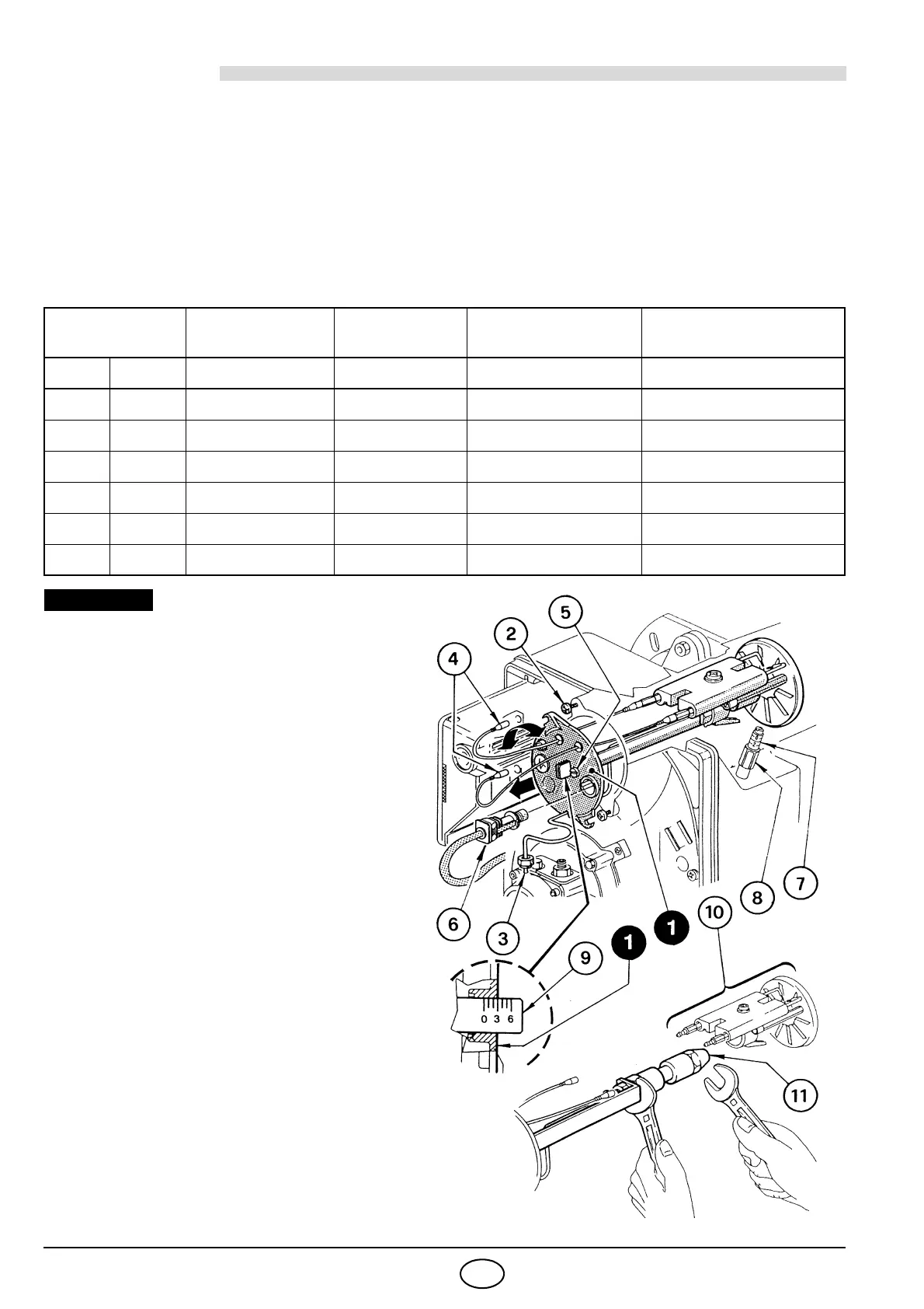
REPLACING NOZZLE, (see fig. 11):
To replace nozzle, proceed as follows:
Disconnect cables (4) from control box and pull
out the photoresistance (6).
Unscrew nut (3), loosen screws (2) and remove
nozzle-holder assembly (1) by rotating slightly to
the right.
Disconnect cables (4) from electrodes, unscrew
screws (3, fig. 12, page 9) and remove the diffus-
er disc support assembly (10) from nozzle-holder
assembly (1).
Nozzle
Pump
pressure
Burner
output
Combustion head
adjustment
Air damper
adjustment
GPH Angle bar kg/h ± 4% Set-point Set-point
2.00 60° 12 8.0 1 2.3
2.25 60° 12 9.0 3 2.6
2.50 60° 12 10.0 3.5 3.0
3.00 60° 12 12.0 5 3.5
3.50 60° 12 14.0 6 4.4
3.50 60° 14 15.2 6 5.6