2862
9
GB
Replace nozzle (11) and screw new one on properly, holding it as illus-
trated in figure 11 at page 8.
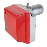
ATTENTION
When refitting the nozzle-holder assembly (1, fig. 11), screw on nut (3)
without tightening it all the way with a driving torque of 15 Nm, as illus-
trated on the right.
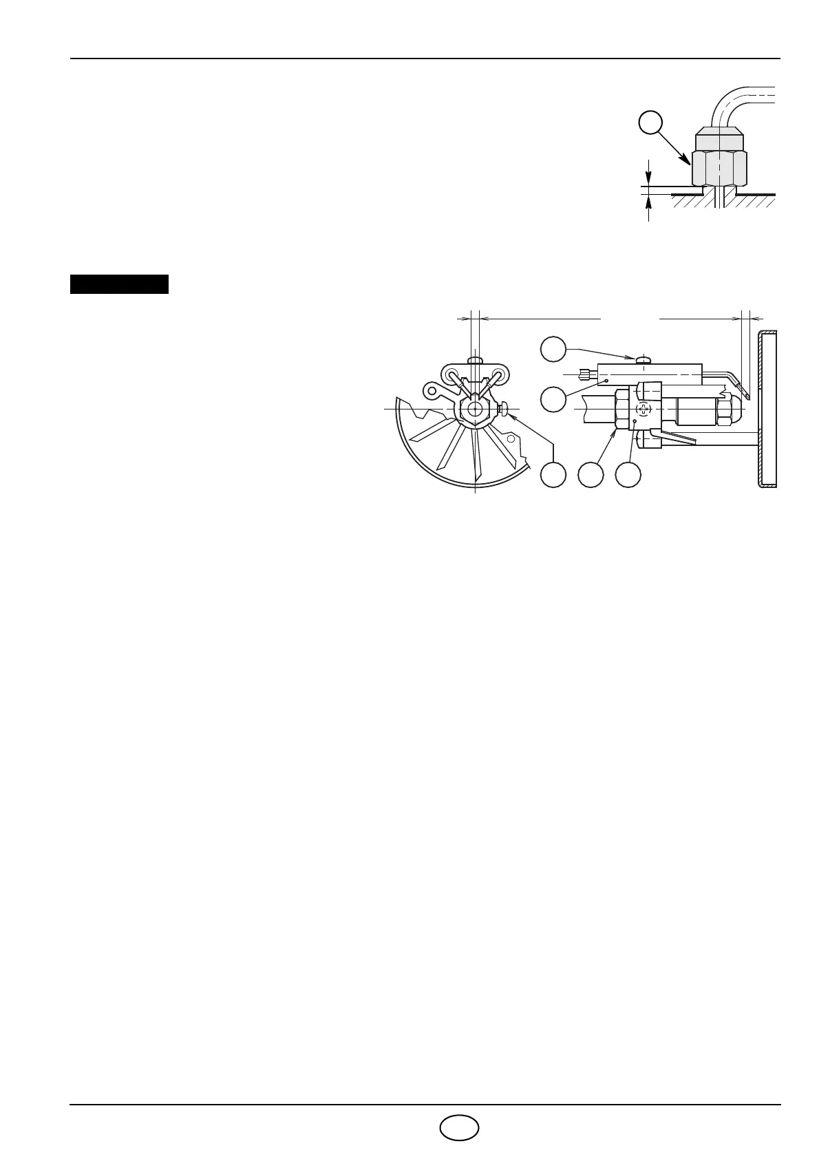
4.3 ELECTRODES ADJUSTMENTS (see fig. 12)
THE GIVEN DISTANCES MUST BE RE-
SPECTED.
To adjust, proceed as follows:
Lean the diffuser disc-holder assembly
(1) on the nozzle-holder (2) and lock it
by screw (3).
For prospective adjustments loosen
screw (4) and move the electrodes as-
sembly (5).
To have access to the electrodes carry out
operation as described in chapter “4.2
RECOMMENDED NOZZLES” (page 8).
4.4 PUMP PRESSURE
The pump leaves the factory set at 12 bar.
Make required adjustments with the aid of the screw (4, fig. 6, page 5).
4.5 COMBUSTION HEAD SETTING, (see fig. 11, page 8)
Combustion head adjustment varies depending on burner delivery.
It depends on the output of the burner and is carried out by rotating clockwise or counterclockwise the setting
screw (5) until the set-point marked on the regulating rod (9) is level with the outside plane of the nozzle-holder
assembly (1).
Figure 11 illustrates the head adjusted for a delivery of 2.25 GPH at 12 bar.
The set-point 3 of the regulating rod (9) is at the same level with the outside plane of the nozzle-holder assembly
(1) as shown in the table at page 8.
4.6 AIR DAMPER ADJUSTMENT, (see fig. 11, page 8)
To adjust air damper, proceed as follows:
Loosen nut (8) and adjust damper setting with the aid of the screw (7).
When burner shuts down the air damper automatically closes till a max. chimney depressure of 0.5 mbar.
Once you have finished adjusting, screw nut (8) back on.
D5085
2
4
3
4,5
– 0,5 mm
0
6
7
mm
1
5
Fig. 12