8
ELECTRICAL SYSTEM
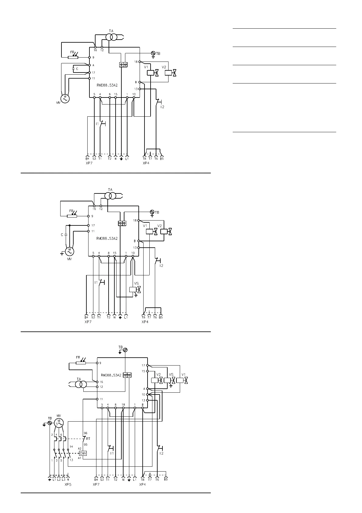
ELECTRICAL SYSTEM as set up by the manu-
facturer
LAYOUT (A)
Burner RL 28 (single-phase)
LAYOUT (B)
Burner RL 38 (single-phase)
LAYOUT (C)
Burners RL 38 - 50 (three-phase)
• Models RL 38 three-phase and RL 50 leave
the factory preset for 400 V power supply.
• If 230 V power supply is used, change the mo-
tor connection from star to delta and change
the setting of the thermal cut-out as well.
Key to Layouts (A) - (B) - (C)
C - Capacitor
CMV - Motor contactor
FR - Photocell
I1 - Switch:
burner off - on
I2 - Switch:
1st - 2nd stage operation
MV - Fan motor
RMO88.53A2 - Control box
RT - Thermal cut-out
TA - Ignition transformer
TB - Burner ground (earth) connec-
tion
V1 - 1st stage solenoid valve
V2 - 2nd stage solenoid valve
VS - Safety solenoid valve
XP4 - 4 pole socket
XP5 - 5 pole socket
XP7 - 7 pole socket
NOTE
For remote-reset, connect a push-button switch
(NO) between terminal 3 and neutral of the con-
trol box (terminals 15, 16, 17 and 18).
RL 28
(A)
ELECTRICAL EQUIPMENT FACTORY-SET
RL 38
ELECTRICAL EQUIPMENT FACTORY-SET
(B)
RL 50
ELECTRICAL EQUIPMENT FACTORY-SET
(C)
20083053
20083051
20083052