20068428
30
Installation
Column 1
Load loss at combustion head.
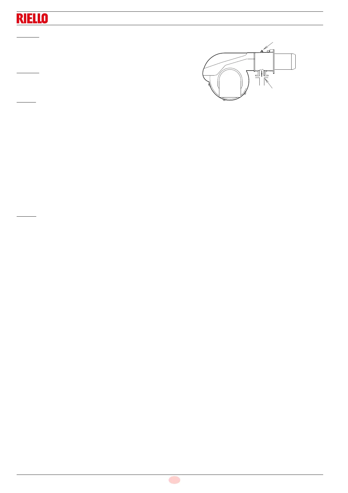
Gas pressure measured at the test point 1)(Fig. 26), with:
• combustion chamber at 0 mbar;
• burner working at maximum output;
Column 2
Pressure loss at gas butterfly valve 2)(Fig. 26) with maximum
opening: 90°.
To know
the approximate output at which the burner is operating
at its maximum:
– Subtract the combustion chamber pressure from the gas
pressure measured at test point 1)(Fig. 26).
– Find, in the Tab. O relating to the burner concerned, column
1, the pressure value closest to the result you want.
– Read the corresponding output on the left.
Example with natural gas G 20 for RS 130/E:
Maximum output operation
Gas pressure at test point 1)(Fig. 26) = 9,0 mbar
Pressure in combustion chamber = 2,0 mbar
9,0 - 2,0 = 7,0 mbar
A maximum output of 1250 kW shown in Tab. O corresponds to
7.0 mbar pressure, column 1.
This value serves as a rough guide; the effective output must be
measured at the gas meter.
To know
the required gas pressure at test point 1)(Fig. 26), set
the maximum output required from the burner operation, then:
– find the nearest output value in the Tab. O for the burner in
question.
– Read, on the right (column 1) the socket pressure 1)(Fig. 26).
– Add this value to the estimated pressure in the combustion
chamber.
Example with natural gas G 20 for RS 130/E:
Required burner maximum output operation: 1250 kW
Gas pressure at output of 1250 kW = 7,0 mbar
Pressure in combustion chamber = 2,0 mbar
7,0 + 2,0 = 9,0 mbar
pressure required at test point 1)(Fig. 26).