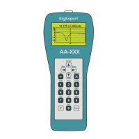
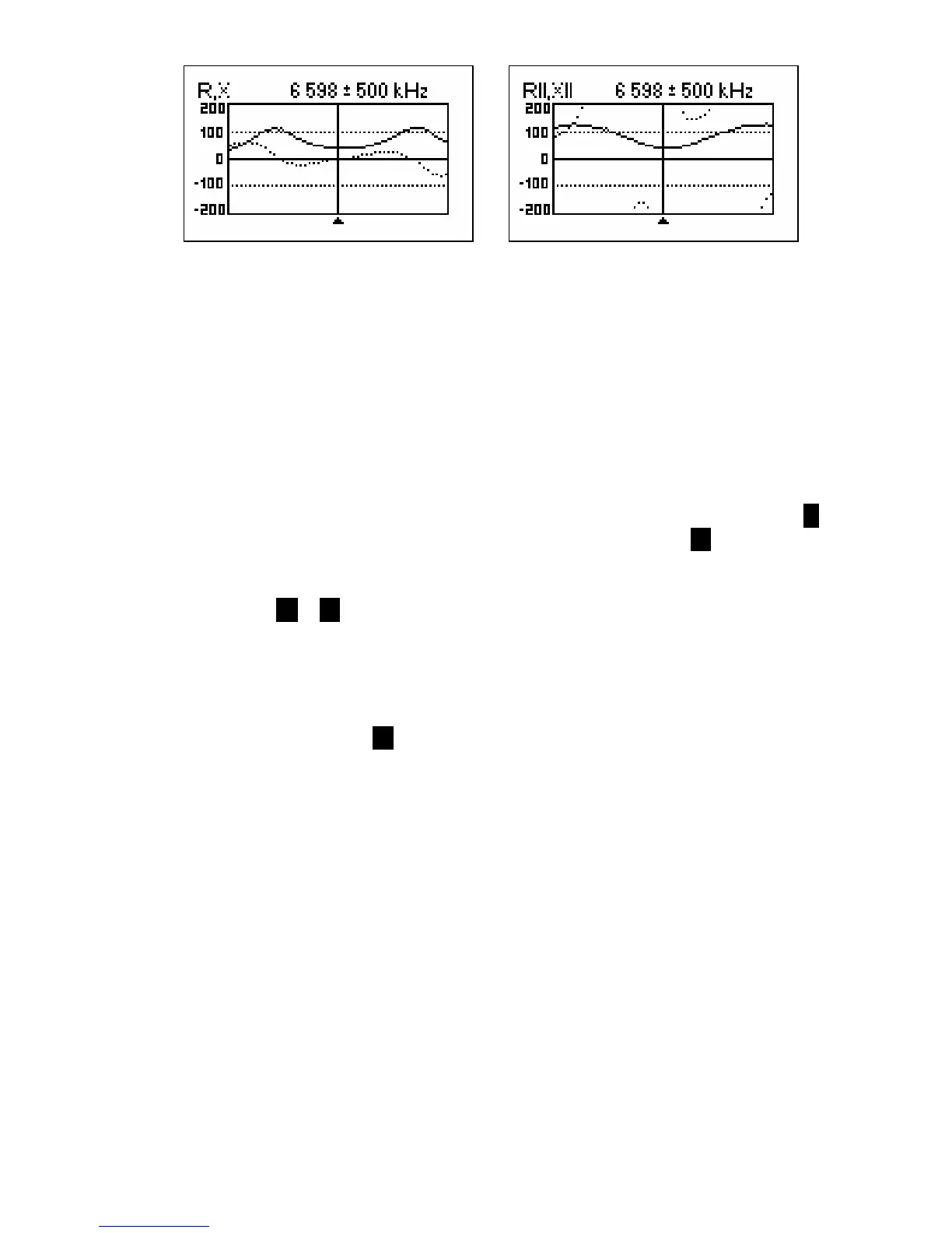
R,X graph - series model R||,X|| graph - parallel model
In these graphs, positive values of reactance (X) correspond to inductive load, while
negative values correspond to capacitive load. Please notice the difference in the plots
when series or parallel model of impedance is selected through the Settings menu.
[Please notice that RigExpert AA-500 displays absolute value of the reactance, |X|.]
4.3.3. Memory operation
In the SWR graph and R,X graph modes, you may choose to scan to memory (the 6
key). There are 100 memory slots available. Later, you may recall ( 9 ) the plots from
the specified memory.
Additionally, the F + 9 combination opens the editor of memory slot names.
4.4. Settings menu
The Settings menu (press the 0 key in the Main menu) contains various settings for the
analyzer.
When setting a longer LCD backlit timer, please notice that the backlit discharges the
accumulator heavily. It is recommended to keep the backlit turned off, when possible.
4.5. Computer connection
RigExpert AA-200/AA-500 Antenna Analyzers may be connected to the personal
computer for displaying measurement results on its screen, taking screen shots of the
LCD, as well as for updating the firmware.
A conventional USB cable may be used for this purpose. The supporting software is
located on the supplied CD.