4. Switch the analyzer to the Show all measurement mode and find values of R at
the previously found frequencies.
Example 1: 54.4 Ohm - max., 51.1 Ohm - min.
Example 2: 75.2 Ohm - max, 52.1 Ohm - min.
5. Calculate the square root of the product of these two values.
Example 1: sqrt (54.4 * 51.1) = 52.7 Ohm
Example 2: sqrt (75.2 * 52.1) = 62.6 Ohm
5.3. Measurement of other elements
Although the analyzer is designed for use with antennas and antenna-feeder paths, it
may be successfully used to measure parameters of other RF elements.
5.3.1. Capacitors and inductors
RigExpert AA-200/AA-500 Antenna analyzers can measure capacitance from a few pF
to about 1 µF as well as inductance from a few nH to about 100 µH.
Be sure to place the capacitor or the inductor as close as possible to the RF connector
of the analyzer.
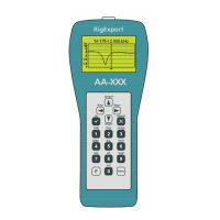
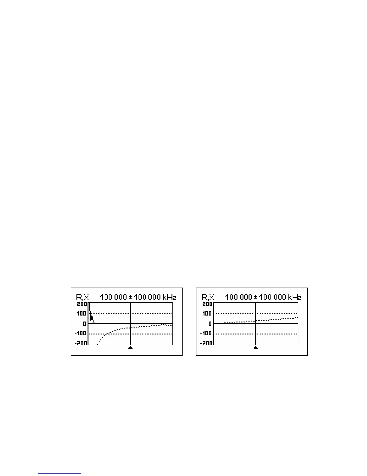
1. Enter the R,X graph mode and select the full scanning range. Perform a scan.
Example 1: Example 2:
Unknown capacitor Unknown inductor
2. By using left and right arrow keys, scroll to the frequency where X is -25…-100
Ohm for capacitors or 25…100 Ohm for inductors. Change the scanning range
and perform additional scans, if needed.
[Please notice that RigExpert AA-500 displays absolute value of the reactance.]
3. Switch to the Show all mode and read the values of capacitance or inductance.