Do you have a question about the Rinnai E- Series and is the answer not in the manual?
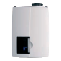
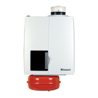
Illustrates and labels the main components of the Rinnai E-Series boiler.
Lists and explains common blocking (bL) and error (E) codes, fuse errors, and indicators.
Provides descriptions for various temperature sensors (T1-T5) used in the boiler.
Addresses the bl05 code related to the outdoor sensor connection or absence.
Troubleshooting for repeated max temp difference between supply and return sensors for CH.
Troubleshooting for repeated max temp difference between supply and return sensors for HW.
Indicates incorrect parameter setting for boiler power (Btu).
Detects temperature difference between T1 and T2 sensors when burner is off.
Indicates T5 sensor reading too high flue gas temperature, check vent blockage.
Relates to flue gas plug moisture issues affecting sensor readings.
Similar to bl81, indicates potential flue gas sensor issues due to moisture.
Indicates an open flue gas thermostat contact, often parameter-related.
Occurs when no water flow is detected, often due to pump or pressure issues.
Occurs when power supply frequency deviates from the norm.
Indicates poor flame formation despite detected ionization flow, often a wiring issue.
Indicates a short circuit within the 24-volt components of the boiler.
Occurs when the boiler fails to ignite gas or receive gas, leading to no flame formation.
Indicates a control unit error, possibly a disconnected connector to the gas valve or wiring harness defect.
Signifies that the controller has detected a program error, often after power cycling.
Indicates a control unit error, potentially due to unstable 120V power supply.
Occurs when the anticipation resistance wire is not present, typically with power-stealing thermostats.
Indicates incorrect data due to poor connection between control unit and display or faulty interface.
Indicates a high limit stat is open or supply temperature is excessively high.
A software error within the control unit, requiring replacement of the control unit.
Indicates a failure in the T3 flow sensor or the controller, often related to ground connection.
Occurs when the maximum flow water temperature (T1) exceeds 212°F.
Occurs when the maximum return water temperature (T2) exceeds 212°F.
Indicates T1 and T2 sensors may be swapped or a temperature failure has occurred.
Requires replacement of the MCBA board or the main board due to an error.
Indicates no feedback signal from the fan motor, meaning the fan is not running.
Occurs due to negative pressure in the vent system, possibly related to fan spin or venting issues.
Indicates a short circuit in the supply sensor T1, usually indicated by low ohm reading.
Indicates a short circuit in the return sensor T2, usually indicated by low ohm reading.
Indicates an open contact for the supply sensor T1, shown by infinite ohm reading.
Indicates an open contact for the return sensor T2, shown by infinite ohm reading.
A software error within the control unit, requiring controller replacement.
A software error within the control unit, requiring controller replacement.
Indicates an electrical short circuit, possibly due to water damage on the MCBA.
Signifies no parameters present, meaning the E-Prom has no program or is blank.
Indicates that no software is present on the MCBA or display/EPROM.
Indicates the T5 sensor reading too high flue gas temperature, possibly due to moisture.
Requires replacement of the MCBA board due to an error.
Instructions for checking and replacing the low voltage fuse on the PC board.
Troubleshooting steps when central heating works but there is no domestic hot water.
Troubleshooting steps when hot water works but there is no central heating.
Addresses central heating getting hot without being requested, often a pump program issue.
Troubleshooting steps for when there is an insufficient quantity of hot water.
Addresses temperature drop issues with Domestic Hot Water (Combi) systems.
Troubleshooting steps for radiators not getting hot enough or warming up too slowly.
Details the procedure for checking and adjusting the O2 percentage for commissioning and fault finding.
Explains the Good-state, Technical Readout, and Operation Indication modes of the boiler display.
Describes the functions and operations of each button on the boiler control panel.
Outlines requirements for the water system, including cleaning, flushing, and water quality.
Details freeze protection requirements using glycol and lists approved antifreeze and inhibitors.
Explains how to fill the system, monitor water pressure, and handle low/high pressure indications.
Describes how to access installer level and adjust various boiler parameters.
Lists and describes parameters for Info, Service, and Error modes for system diagnostics.
Procedure for resetting all boiler adjustments back to their original factory settings.
Instructions on how to isolate the boiler by switching off its main components.
Steps to reset the service notification and countdown after 4000 hours of use.
| Fuel Type | Natural Gas or Propane |
|---|---|
| Installation | Wall-mounted |
| Type | Condensing |
| Venting | Direct Vent |
| Dimensions | Varies by model |
| Weight | Varies by model |
| Warranty | 12 years heat exchanger, 5 years parts |
| Heating Capacity | 15, 000 - 199, 000 BTU/h |
| Vent Type | Direct Vent |