22 KBD Series Manual
All PVC/CPVC IPEX Concentric Vent Kit (CVK)
Assemblies are cered to ULC S636. Where ULC S636
compliance is required, use only System 636 pipe,
ngs, and cement at terminal connecon.
use PVC/CPVC on Non-Condensing Units.
operate unit unl venng is completely
installed and all solvents and glues have bonded.
All PVC/CPVC exhaust vent material used in
Canada must be S636 cered.
For further details on listed PVC/CPVC venng
material (table below) refer to the installaon manual of
the PVC/CPVC manufacturer.
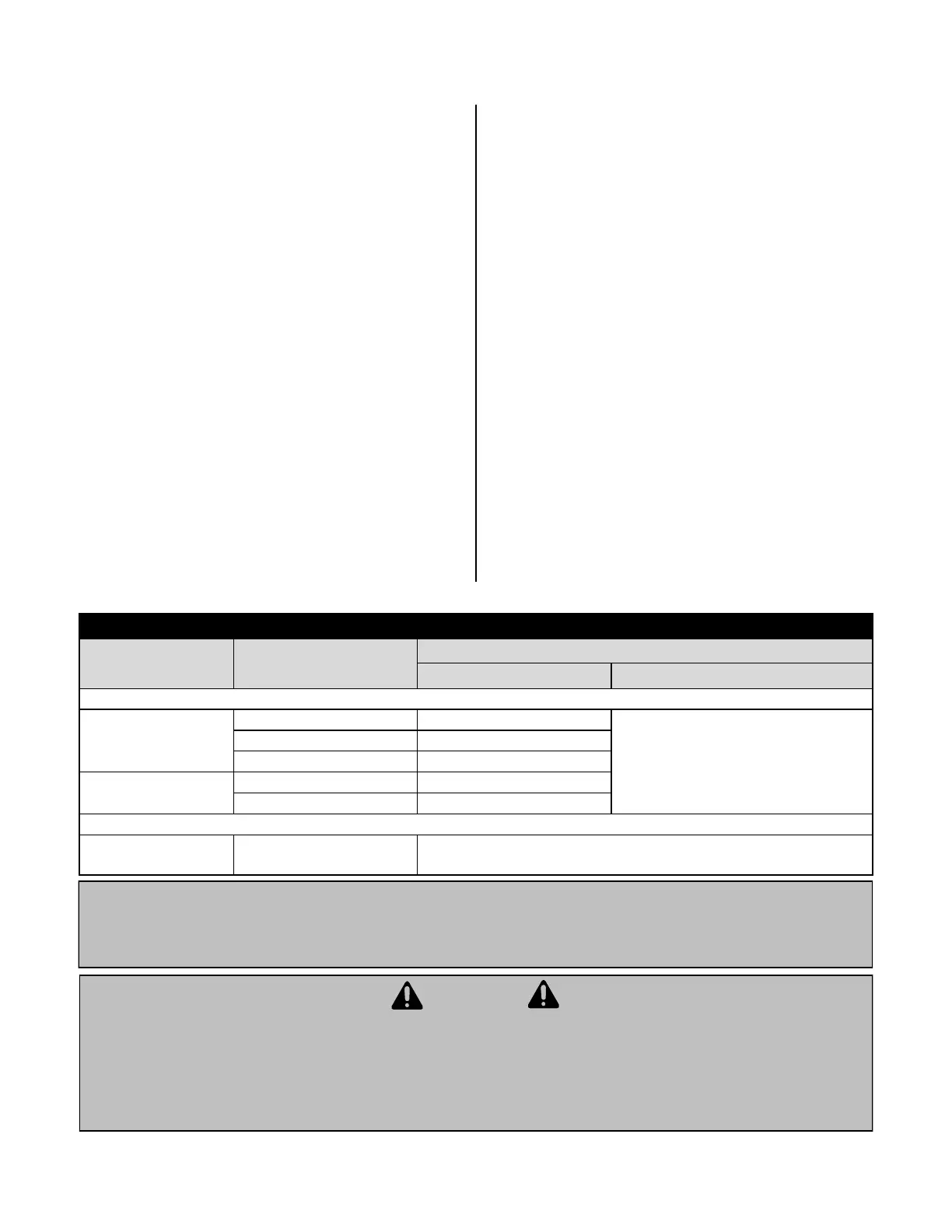
Twin Pipe PVC/CPVC Vent Installaon Requirments:
Vent or combuson air
intake pipe & Fings
PVC schedule 40 ANSI/ASTM D1785
Thermoplasc vent pipe must be
cered to ULC S636.
Intake pipe may be of any material listed
(le).
PVC-DWV ANSI/ASTM D2665
CPVC schedule 40 ANSI/ASTM F441
PVC pipe cement &
primer
PVC ANSI/ASTM D2564
CPVC ANSI/ASTM F493
Terminaon Vent
Screens
Polyethylene
3" Vent screen: IPEX part # 196051; 4" Vent screen: part #: 196052
(Screens are fricon ed inside terminaon ng bells.)
The listed vent, vent ngs, terminaon, cleaner, and glue are all cered as part of the condensing tankless
water heater vent system.
Failure to correctly install vent and combuson air intake pipes of the water heater to atmosphere as outlined
in this venng secon will result in death from asphyxiaon (from carbon monoxide), re, or explosion.
operate the water heater without proper venng (vent and combuson air intake). Always inspect the vent
terminal unit, combuson air intake pipe, and the enre vent system axed to the water heater for proper
installaon at equipment commissioning and at least annually thereaer.
Locate the vent outlet where ue gases will not harm
surrounding plants and/or cooling equipment.
Avoid locang vent where prevailing winds could
aect the performance of the water heater or cause
recirculaon of the ue gases.
terminate the venng over a public walkway
or over an area where condensate or vapor can
create a nuisance / hazard or where condensate can
be detrimental to the operaon of equipment such as
regulators or relief valves
Water Heater ue gases must be piped from the
appliance to the outside, Installer MUST adhere to the
instrucons provided herein and the most
recent Water Heater Manual and all applicable codes.
Exhaust and combuson air must terminate through
the same sidewall or roof as the terminaons must be
in the same pressure zone and face same direcon.
Vent pipe must terminate either through the sidewall
or through the roof, exhaust/vent terminaon and/or
intake air openings shall adhere to clearances as set
forth in the Direct Vent Terminaon Clearances
diagram.
Each Condensing Tankless Water Heater requires a
separate vent system.
If common venng is required, refer to Rinnai
Common Vent Installaon Manual (latest revision) for
instrucons on specic allowable venng method as
well as to verify which tankless models may be
common vented.
For twin pipe installaon use only 3” or 4” PVC/CPVC.
Terminaons must be installed 12” above grade or
ancipated snow level.
 Loading...