Rinnai Australia - 61 - Solar Split Systems Operating / Installation Manual Version 9 - 21/11/12
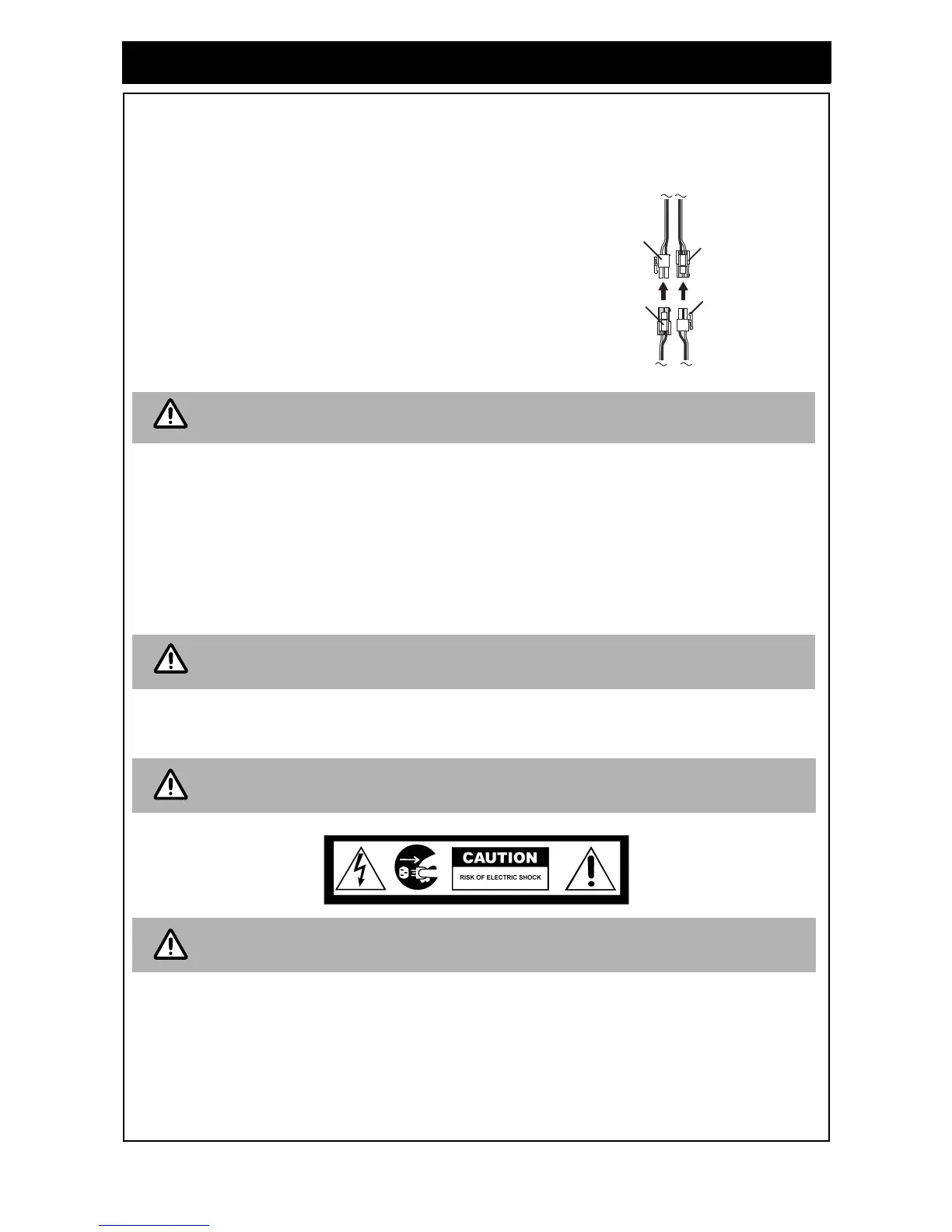
7. Connect Temperature Sensor Leads
• The hot (longer) temperature sensor lead should be fitted into the air bleed / hot sensor lead
assembly at the collector hot return connection as shown in Figures 42 to 45. It must be sealed
in place with thermoplastic putty or silicone.
• Run the lead down the solar return pipe and connect it to
the connection within the pump and controller assembly
as shown in the diagram below. Ensure the lead is
protected from light.
• The cold (shorter) temperature sensor lead should be
fitted as shown in the relevant diagram in Figures 42 to
45. Ensure the lead is protected from sunlight. It must be
sealed in place with thermoplastic putty or silicone. The
plug is then connected to the pump and controller
assembly as shown in the diagram.
• Replace pump assembly cover.
8. Cold Water Supply
• Connect cold water supply to the inlet ‘T’. Ensure that the relevant valves as described in the
section “VALVES AND FITTINGS” are fitted.
• Purge the cold water supply lines to remove air and swarf before final connection.
9. Relief Drain Lines
• Independent 15 mm copper pipes must be fitted to the drain outlets of the PTR and ECV. Each
pipe must be open to atmosphere and run with a continual downward grade in a frost free
environment to a visible discharge point. Drain lines must not exceed 9 metres in length.
• Valves or other restrictions must not be placed in the relief valve drain outlet line.
10.Hot Water Discharge
• Connect the hot water outlet of the storage cylinder to the pipe work supplying hot water to the
premises.
11.Electrical Supply Connections
• Twin element storage cylinders are wired for non simultaneous operation. The electric supply
should be ‘Off-Peak’ (overnight) to the bottom heating unit and continuous to the top heating unit.
• The power supply to a single lower element model should be Off-Peak (overnight).
• The power supply to a single mid element model can be either Off-Peak (overnight), extended Off-
Peak (overnight and day) or continuous, depending on the tariffs available from the local electricity
supply authority. The Off-Peak (overnight) power supply minimses the cost of any required electric
boosting, but may not provide sufficient hot water in periods of low solar gain. Discuss power
supply requirements with the end user and electricity supply authority as required.
IT IS IMPORTANT THAT THESE PROBES ARE INSTALLED AS SPECIFIED.
FAILURE TO DO SO WILL LEAD TO MALFUNCTION OR LACK OF HOT WATER.
Some water will drip from the drain lines during heating of the water in the storage
cylinder. It is recommended to discharge directly above a drain.
A temperature limiting device may be required as detailed in the section “HOT
WATER DELIVERY TEMPERATURE”.
The power supply to the heating elements and pump kit must not be activated until the
system is filled with water.