Natural draft Fan assisted
• Appliances 002003tupni h/JM 05 ot pu
• Appliances 003005tupni h/JM 05 revo
003003* ecafrus rehto ro ynoclab a evoba ,dnu
org eht morFb
003005* renroc lanretxe ro llaw nruter a tnorFc
d
From a gas meter (M) (see 5.11.5.9 for vent terminal location of regulator )
00010001)stnemeriuqer dnalaeZ weN r
of 6.6 elbaT ees(
e From an electricity meter 005005† )P( xob esuf ro
57051epip lios ro epip niard a morFf
g Horizontally from any building structure* = or obstruction facing a terminal 500 500
h From any other flue terminal , cowl, or combustion air intake † 500 300
• Appliances 003005* tupni h/
JM 051 ot pu
• Appliances over 150 MJ/h input up to 200 MJ/h input * 1500 300
• Appliances over 200 MJ/h input up to 250 MJ/h input * 1500 500
• Appliances 00510051* tupni h/JM 052 revo
• All fan-assisted flue appliances , in the direction of discharge - 1500
00010051rewolb aps a gnidulcni ,telni ria laci
nahcem a morFk
051051tupni rh/JM 05 ot pu sretaeh ecapS •
• Other appliances 005005tupni rh/JM 05 ot pu
• Appliances over 50 MJ/h input and up to 150 MJ/h input 1000 1000
• Appliances 00510051tup
ni h/JM 051 revo
1
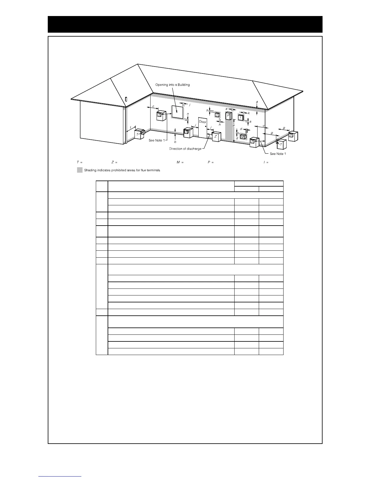
Where dimensions c, j or k cannot be achieved an equivalent horizontal distance
measured diagonally from the nearest discharge point of the terminal to the opening
may be deemed by the Technical Regulator to comply.
2
See Clause 6.9.4 for restrictions on a flue terminal under a covered area.
3
See Figure J3 for clearances required from a flue terminal to an LP Gas cylinder.
A flue terminal is considered to be a source of ignition.
4
metI.feR
a
Min. clearances (mm)
Below eaves, balconies and other projections:
j
Horizontally from an openable window, door, non-mechanical air inlet, or any other opening into a building
with the exception of sub-floor ventilation:
Vertically below an openable window, non-mechanical air inlet, or any other opening into a building with the
exception of sub-floor ventilation:
NOTES:
† - Prohibited area below electricity meter or fuse box extends to ground level.
FIGURE 6.2 (in-part) MINIMUM CLEARANCES REQUIRED FOR BALANCED FLUE TERMINALS, FAN-ASSISTED
FLUE TERMINALS, ROOM-SEALED APPLIANCE TERMINALS AND OPENINGS OF OUTDOOR APPLIANCES
* - unless appliance is certified for closer installation
For appliance s not addressed above acceptance should be obtained from the Technical Regulator.
n
Flue terminal Fan assisted flue appliance only Gas meter Electricity meter or fuse box Mechanical air inlet