Rinnai Australia - 60 - Solar Split Systems Operating / Installation Manual Version 9 - 21/11/12
INSTALLATION PROCEDURE
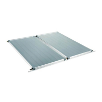
1. Install Solar Collectors
Position and install the solar collectors in accordance with the section ‘INSTALLATION OF SOLAR
COLLECTORS’.
2. Position Storage Cylinder
Position the hot water storage cylinder on a level base in accordance with the section “STORAGE
CYLINDER LOCATION”.
3. Connect PTR Valve
• Connect the PTR Valve in the location shown in the relevant diagram of Figures 42 to 45.
Leave the valve outlet pointing down. Tighten the valve using the spanner flats - never use the
valve body.
• The PTR Valve must be adequate for the thermal loading applied to the storage cylinder. In the
case of gas boosted systems, the thermal load is applied only by the solar collectors. The
continuous flow hot water heater does not apply thermal load to the storage cylinder. The
potential solar output for the solar collectors at PTR Valve relief conditions is listed in Table 3.
• The PTR Valve pressure ratings vary according the cylinder specifications. The maximum heater
input rating is 10.0 kW. The PTR valve rating MUST EXCEED the total input from the solar
collectors. If it does not, the PTR valve MUST be exchanged for a model of higher capacity. For
an electric boost system, the energy from the solar panels and the electric element(s) needs to
be considered. The maximum potential solar input is listed in Table 5.
• For example, A twin element 3.6 kW cylinder with 3 x SP200A panels will have a maximum
energy input of 3 x 1.25 + 2 x 3.6 = 10.95 kW, therefore a higher capacity P&TR valve will be
required.
• Use Teflon thread tape on the valve, never use hemp or other sealing materials. Ensure the tape
does not protrude past the end of the thread, which could result in it hanging over the end of the
thread and blocking the water passage through the valve.
4. Connect Fittings and Mount Pump Assembly
• Connect fittings and pipe work as shown in the relevant diagram in Figures 42 to 45. Remove
cover of pump box and attach pump box to cylinder using screws provided. Do not connect the
power lead to power supply at this stage.
5. Set Frost Protection Mode
Adjust Dip Switches on solar controller to give the required frost protection. (Refer to Page 19).
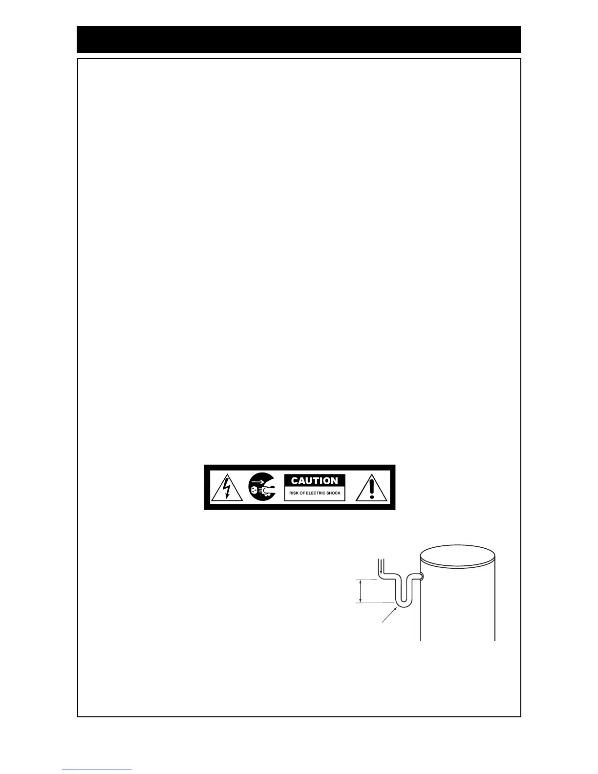
6. Install and Connect Flow and Return Pipe Work
• Connect flow and return pipe work between storage
cylinder and solar collector. Ensure that suitable pipe and
insulation is used as described in the section "WATER
PIPES".
• A heat trap is recommended on the return line from the
cylinder if the pipework is to rise vertically to prevent heat
losses due to the thermosyphoning of hot water from the
tank.
Figure 38 - Heat Trap