3 Product description
EN
16 Rittal roof-mounted Blue e+ cooling unit/VX25 Blue e+ integration solution
Please observe the prescribed minimum distances at
the installation site as outlined in section 5.3.1 "As-
sembly instructions".
There is a risk of cut injuries when working on the unit.
Wear personal protective equipment, consisting of at
least cut-resistant gloves.
There is a risk of injuries when lifting and transporting the
unit.
Note the maximum permitted weights that may be lift-
ed by individuals.
Lift the roof-mounted cooling unit by two persons or
use lifting gear.
Lift the integration solution only with suitable lifting
gear.
3 Product description
3.1 Functional description and components
3.1.1 Function
There are two separate cooling circuits installed in the
cooling unit.
– One conventional refrigerant circuit (compression sys-
tem), and
– One heat pipe integrated into the condenser and
evaporator coil.
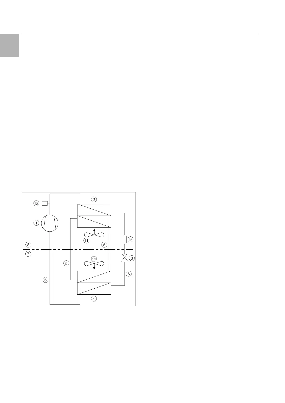
Fig. 1: Cooling circuit
Key
1 Compressor
2 Condenser (dual version) with fan
3Expansion valve
4 Evaporator coil (dual version) with fan
5 Refrigerant circuit with heat pipe
6 Refrigerant circuit with compression system
7 Internal circuit
8 External circuit
9 Dryer/collector
10 Internal fan
11 External fan
12 PSA
H
pressure monitor
In both cooling circuits, the individual components are
connected with pipes in which the refrigerant R134a is
circulating. This refrigerant is very environmentally friend-
ly, thanks to the following properties:
– Chlorine-free
– Does not deplete the ozone layer (ozone destruction
potential ODP = 0)
Refrigerant circuit with compression system
The refrigerant circuit with compression system is com-
prised of the following four main components:
1. Evaporator coil
2. Compressor
3. Condenser
4. Expansion valve
The evaporator coil fan draws hot air from the enclosure
in the internal circuit of the cooling unit and passes it
over the evaporator coil. After the evaporator coil, the
cooled air is fed back into the enclosure via the outlet
opening.
The air is cooled down by evaporating the refrigerant in
the evaporator coil. The refrigerant vapour is transported
by the compressor in the external circuit of the cooling
unit to the condenser. There, the refrigerant condenses
and becomes a liquid. The heat produced is dissipated
by the condenser fan. The downstream electronic ex-
pansion valve reduces the high pressure of the refriger-
ant, and the refrigerant is then fed back into the evapo-
rator coil.
Both the compressor and the two fans in the cooling unit
are activated via an inverter. This makes it possible to
control these components, so that the fan and compres-
sor may be activated for a longer time but at a lower out-
put and improved efficiency.
Refrigerant circuit with heat pipe
The additional second refrigerant circuit operates with-
out a compressor, expansion valve or other control ele-
ments, and is integrated into the evaporator coil and
condenser as a heat pipe.
The refrigerant inside the heat pipe (R134a) absorbs
thermal energy from the intake of enclosure air and
evaporates. The gaseous refrigerant then rises through
the pipeline until it reaches the condenser. The refriger-
ant is cooled down again in the condenser (provided Tu
< Ti), and the heat released is emitted into the environ-
ment. Gravity then causes the liquid refrigerant to flow
back down the pipelines. The whole cycle begins again.