Rittal roof-mounted Blue e+ cooling unit/VX25 Blue e+ integration solution 27
5 Installation
EN
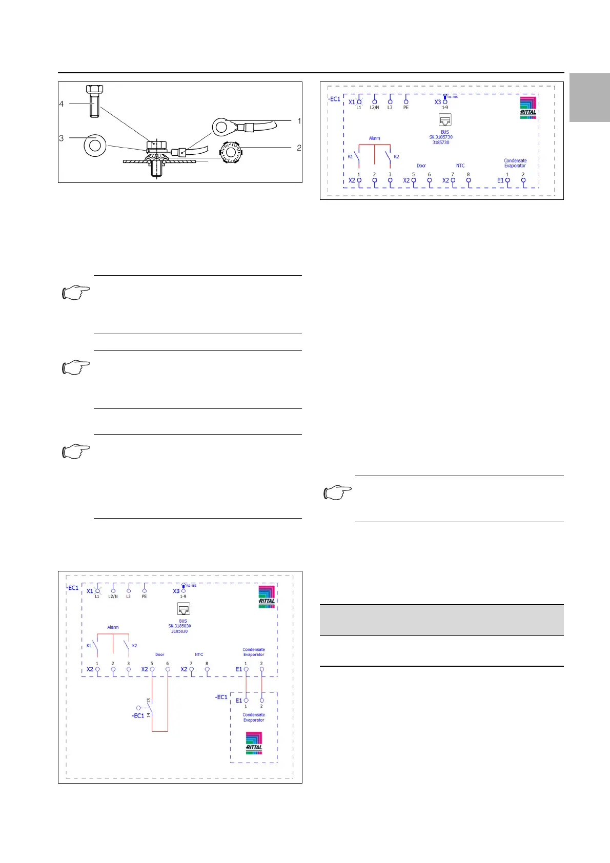
Fig. 15: Potential equalisation arrangement
Key
1 Ring terminal with PE conductor
2 Contact washer
3Washer
4 Screw
5.4.2 Install the power supply
Remove the mains connector from the dispatch bag
and connect to the mains as shown on the connection
diagram (fig. 16 or fig. 17).
Fig. 16: Circuit diagram 3185030
Fig. 17: Circuit diagram 3185730
Key
X1 Main terminal strip
K1 Relay collective fault 1
K2 Relay collective fault 2
Door Door limit switch (optional for 3185730, without door lim-
it switch: terminal 5, 6 open)
NTC External temperature sensor (optional)
X3 RS 485 interface for IoT Interface (3124.300)
Create a strain relief
For the roof-mounted cooling unit, take the T-rail from
the dispatch bag and attach it to the connection unit.
The T-rail is already pre-installed for the integration
solution.
Then establish the strain relief on the T-rail using cable
ties.
5.4.3 Connect the alarm relays
System messages from the cooling unit may be output
to an external signal source via two floating relay out-
puts.
Connect a suitable connection cable to the connec-
tion terminals 1 (Alarm K1) and/or 3 (Alarm K2) of the
signal connector (X2).
Configure the alarm relays you wish to use to output
error messages (see section 7.4.3 "Alarm relays").
5.4.4 Interfaces
The cooling unit has the following interfaces for commu-
nicating with external systems:
– Micro-USB interface on the front
– RS 485 interface at the bottom
Note:
According to the standard, the PE conductor
in the mains connection cable is not classed
as an equipotential bonding conductor.
Note:
The enclosure of the integration solution or
the enclosure on which the cooling unit is
mounted must be grounded.
Note:
– The mains supply must be shielded with
EMC preferred type to achieve the values
demanded by the standard.
– The cable shield can make contact with the
T-rail (fig. 13, item 1).
Note:
The factory setting of the relay outputs in their
de-energised state is NO (Normally Open).
AC
cos φ = 1
I max. = 2 A
U max. = 250 V
Tab. 5: Contact data