5 Installation
EN
26 Rittal roof-mounted Blue e+ cooling unit/VX25 Blue e+ integration solution
– The units are high-voltage tested ex works. An addi-
tional high voltage test must only be carried out with a
DC voltage supply source (1500 VDC max.).
– If the combined output of the frequency converters,
power converters or transformers in the network
where the device is being operated is >70 kVA, the
customer must connect a Class II surge voltage pro-
tector in the mains supply line upstream of the cooling
unit. The surge voltage protector must be designed to
EN 61800 -1. The following values may be assumed
as starting-points for the design:
Three-phase devices
– There is no need to observe a counterclockwise or
clockwise phase rotation when making the electrical
connection for inverter devices in the three-phase ver-
sion. The electronics incorporated into the devices au-
tomatically create the required phase rotation.
– In three-phase devices, the absence of a phase is de-
tected, and the device is switched off.
– Outgoing equipment is monitored by the inverter, and
deactivated in the event of a malfunction in the elec-
tricity supply.
Door limit switch
– Each door limit switch can only be assigned to one
cooling unit.
– Several door limit switches may be operated in parallel
with one cooling unit.
– The minimum cross-section for the connection cable
is 0.3 mm² for a cable length of 2 m.
– The line resistance to the door limit switch must not
exceed a maximum of 50 Ω.
– The maximum admissible line length is 10 m.
– The door limit switch only supports a floating connec-
tion; no external voltages.
– The contact of the door limit switch must be closed
when the door is open.
– The safety extra-low voltage for the door limit switch is
provided by the internal power pack: Current approx.
5mA DC.
Connect the door limit switch to terminals 5 and 6 of
the signal connector.
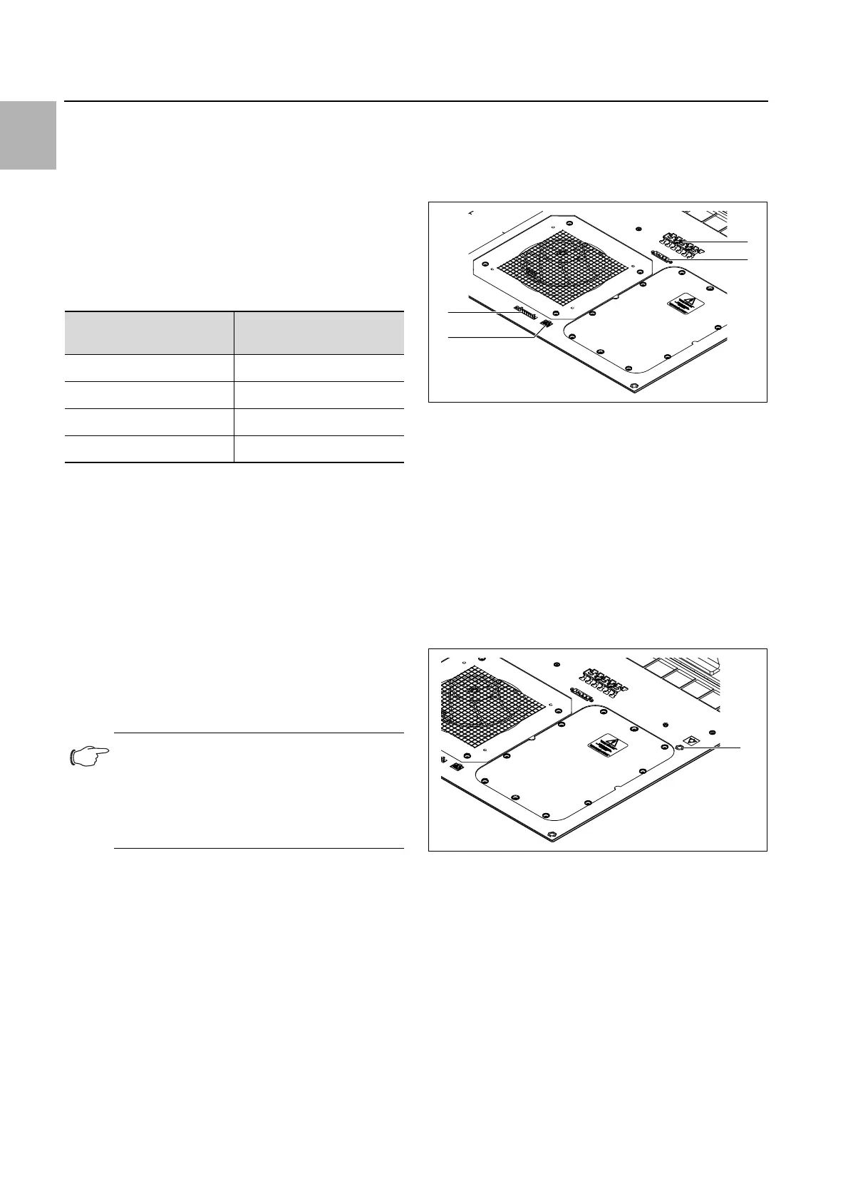
Fig. 13: Fasteners at the bottom of the roof-mounted cooling
unit
Key
1 T-rail for strain relief
2 Connection for mains connector (X1)
3 Connection for IoT interface 3124.300 (X3)
4 Connection for signal connector (X2)
Potential equalisation
If, for EMC reasons, the unit is to be integrated into the
customer's existing potential equalisation system, a
conductor may be connected to the potential equalisa-
tion connection point. The connection point is labelled
with the required switch symbol.
Fig. 14: Connection point for potential equalisation
Key
1 Connection point M6
Attach the potential equalisation to the unit's connec-
tion point using the screw, washer and contact wash-
er.
Transformers,
power electronics
Assumed discharge
energy
70 kVA…100kVA 40J
100 kVA…200kVA 80J
200 kVA…400kVA 160J
400 kVA…800kVA 320J
Tab. 4: Design of the surge voltage protector
Note:
The door limit switch is installed in the enclo-
sure as standard for the integration solution.
Consequently, the following description ap-
plies only to the Blue e+ roof-mounted cool-
ing unit.
1