Rittal roof-mounted Blue e+ cooling unit/VX25 Blue e+ integration solution 25
5 Installation
EN
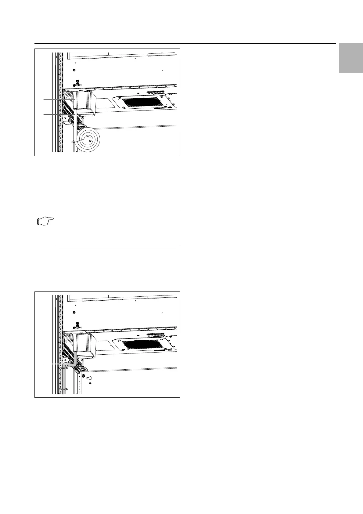
Fig. 11: Condensate water discharge hose on the condensate
evaporator
Key
1 Condensate evaporator
2 Condensate water discharge hose at the bottom of the
condensate evaporator (emergency discharge)
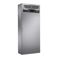
When the integration solution is located on the VX
base/plinth system available as accessory: route the
discharge hose downwards in accordance with the
above-mentioned notes through the base from the en-
closure (fig. 12).
Fig. 12: Laying the hose (sample representation)
Key
1 Hose with cable ties on the enclosure frame
As an alternative or when the integration solution is not
placed in the base/plinth system, route the hose out-
wards through the side panel of the enclosure.
Drill a hole (Ø 20.5 mm) at an appropriate location in
the side panel.
Place the supplied grommet in this hole to provide the
enclosure degree of protection.
Then route the hose from the enclosure through the
grommet in accordance with the above-mentioned
notes.
5.4 Electrical connection
5.4.1 Notes on electrical installation
When carrying out the electrical installation, it is impor-
tant to observe all valid national and regional regula-
tions as well as the provisions of the responsible
power supply company.
– Electrical installation must only be carried out by a
qualified electrician who is responsible for compliance
with the existing standards and regulations.
– All cables routed into the wiring compartment have to
be insulated for the maximum voltage of the power
supply.
Connection data
– The connected voltage and frequency must corre-
spond to the ranges stated on the rating plate. The
units support multiple voltages.
– The cooling unit must be connected to the mains via
an all-pole disconnect to overvoltage category III (IEC
61058-1).
– No additional temperature control may be connected
upstream of the unit at the supply end
– To ensure the proper functioning of internal safety de-
vices in the event of a malfunction, a line fuse not less
than 15 A and of type "Slow (Time Delay CCMR)" or
one of the following UL-listed circuit-breakers (DIVQ/7)
is required:
– 3RV2711-4AD10 by SIEMENS (E235044) rated
15 A
– FAZ-C15/3-NA by EATON (E235139) Class curve C
rated 15 A
– FAZ-D15/3-NA by EATON Class curve D rated 15 A
– If a motor circuit-breaker or circuit-breaker is used, it
should be selected in accordance with EN 60898-1
(tripping characteristic type D).
– Low-noise potential equalisation must be guaranteed
with the mains connection.
Overvoltage protection and supply line load
– The unit does not have its own overvoltage protection.
Measures must be taken at the supply end by the
switchgear manufacturer or operator to ensure effec-
tive protection against lightning and overvoltage.
– The units are classified as overvoltage category III. The
mains voltage must not deviate by more than the tol-
erance specified in section 10 "Technical specifica-
tions".
– The discharge current may exceed 3.5 mA.
Note:
Under no circumstances may the conden-
sate hose be removed from the condensate
evaporator.