Rittal Liquid Cooling Package 13
3 Device description
EN
3.3 Equipment assembly
3.3.1 Schematic design
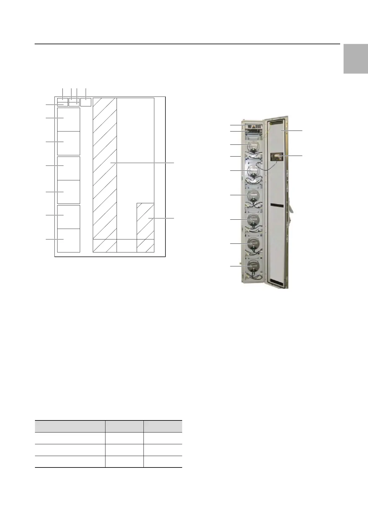
The schematic design is illustrated below:
Fig. 10: Schematic design of a Liquid Cooling Package –
right-hand side view
Key
1 Fuse box with master switch (see fig. 11, item 6)
2 Water PCB
3 Fan PCB
4 Startup current limitation
5 Air/water heat exchanger
6 Water module
7 Fan 6 (not with LCP Inline flush)
8 Fan 5 (not with LCP Inline flush)
9 Fan 4
10 Fan 3
11 Fan 2
12 Fan 1
13 Control unit CMC III PU (see fig. 11, item 5)
The Liquid Cooling Package consists of a fuse box, a
superordinate control unit (CMC III PU), a water mod-
ule, a heat exchanger, and the fan modules. In its sup-
plied state, the following fan modules are built into the
devices:
Tab. 1: No. of fan modules in supplied state
The fan modules and the water module contain their
own electronic controls (1 x RLCP fan and 1 x RLCP
water), which are connected to the CMC III PU via a
CAN bus. The fan modules are switched on sequen-
tially from one to six (or one to four with
LCP Inline flush) via a startup current limitation once
connected to the mains voltage.
3.3.2 Unit components
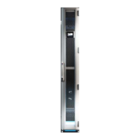
Fig. 11: Liquid Cooling Package front – open front door
(60 kW variant)
Key
1 LCP door
2 Optional display with touch function (rear)
3 Fans (in this instance, fully equipped with 6 fans)
4 Rack
5 Control unit CMC III PU (see fig. 10, item 13)
6 Fuse box with master switch (see fig. 10, item 1)
Device/cooling output 30 kW 55 kW
LCP Rack 1 module 4 modules
LCP Inline 1 module 4 modules
LCP Inline flush 2 modules –
11
9
7
6
12
10
8
13
5
1234
1
2
6
5
3
3
3
3
4
3
3
 Loading...