16 Further technical information
EN
84 Rittal Liquid Cooling Package
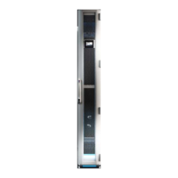
16.4.1 Control unit hardware for the fan modules
(RLCP fan)
Fig. 91: Control unit fan module – rear/top view
Key
1 Control Interface socket (X1) – RJ45
2 Control Interface socket (X2) – RJ45
3 Temperature sensors, cold air socket (X3) – 6-pole
4 Temperature sensors, hot air socket (X4) – 6-pole
5 Fan setpoint sockets (X5) – 24-pole
6 Debugger
7 LED yellow (2x)
8 LED green (2x)
9 Earth (4x)
X1 / X2 pin assignment:
1 CAN 1/2 high
2CAN 1/2 low
3+24V
4GND
5GND
6+24V
X5 pin assignment:
1 SET_1 setpoint fan 1
2 10 V from fan 1
3 SET_2 setpoint fan 2
4 10 V from fan 2
5 SET_3 setpoint fan 3
6 10 V from fan 3
7 SET_4 setpoint fan 4
8 10 V from fan 4
9 SET_5 setpoint fan 5
10 10 V from fan 5
11 SET_6 setpoint fan 6
12 10 V from fan 6
13 SPD_1 actual value, fan 1
14 GND fan 1
15 SPD_1 actual value, fan 2
16 GND fan 2
17 SPD_3 actual value, fan 3
18 GND fan 3
19 SPD_4 actual value, fan 4
20 GND fan 4
21 SPD_5 actual value, fan 5
22 GND fan 5
23 SPD_6 actual value, fan 6
24 GND fan 6
X3 pin assignment:
1 GND temperature sensor 1 cold air
2 GND temperature sensor 2 cold air
3 GND temperature sensor 3 cold air
4 Temperature sensor 1 cold air
5 Temperature sensor 2 cold air
6 Temperature sensor 3 cold air
X4 pin assignment:
1 GND temperature sensor 1 hot air
2 GND temperature sensor 2 hot air
3 GND temperature sensor 3 hot air
4 Temperature sensor 1 hot air
5 Temperature sensor 2 hot air
6 Temperature sensor 3 hot air
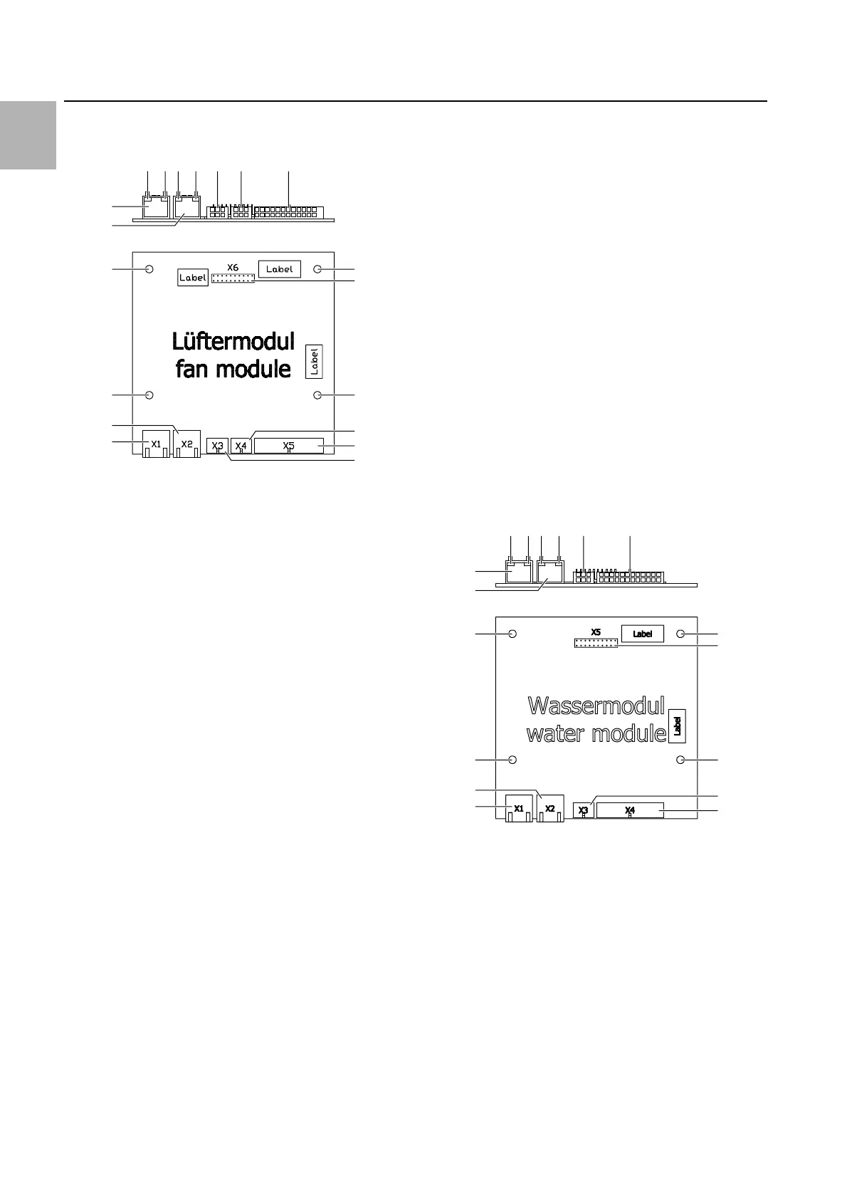
16.4.2 Control unit hardware for the water module
(RLCP water)
Fig. 92: Control unit water module – rear/top view
Key
1 Control Interface socket (X1) – RJ45
2 Control Interface socket (X2) – RJ45
3 Condensate pump controller socket – 6-pole
4 Sensors and actuators socket – 24-pole
5 Debugger
6 LED yellow (2x)
7 LED green (2x)
8 Earth (4x)
X1 / X2 pin assignment:
1 CAN 1/2 high
2 CAN 1/2 low
3+24V
4GND
5GND
6+24V
9
9
9
9
1
2
5
4
3
1
2
3
457878
6
8
8
8
8
1
2
4
3
1
2
3
46767
5
 Loading...