7. Working life
55
DeutschEnglishFrancaisEspanolItaliano
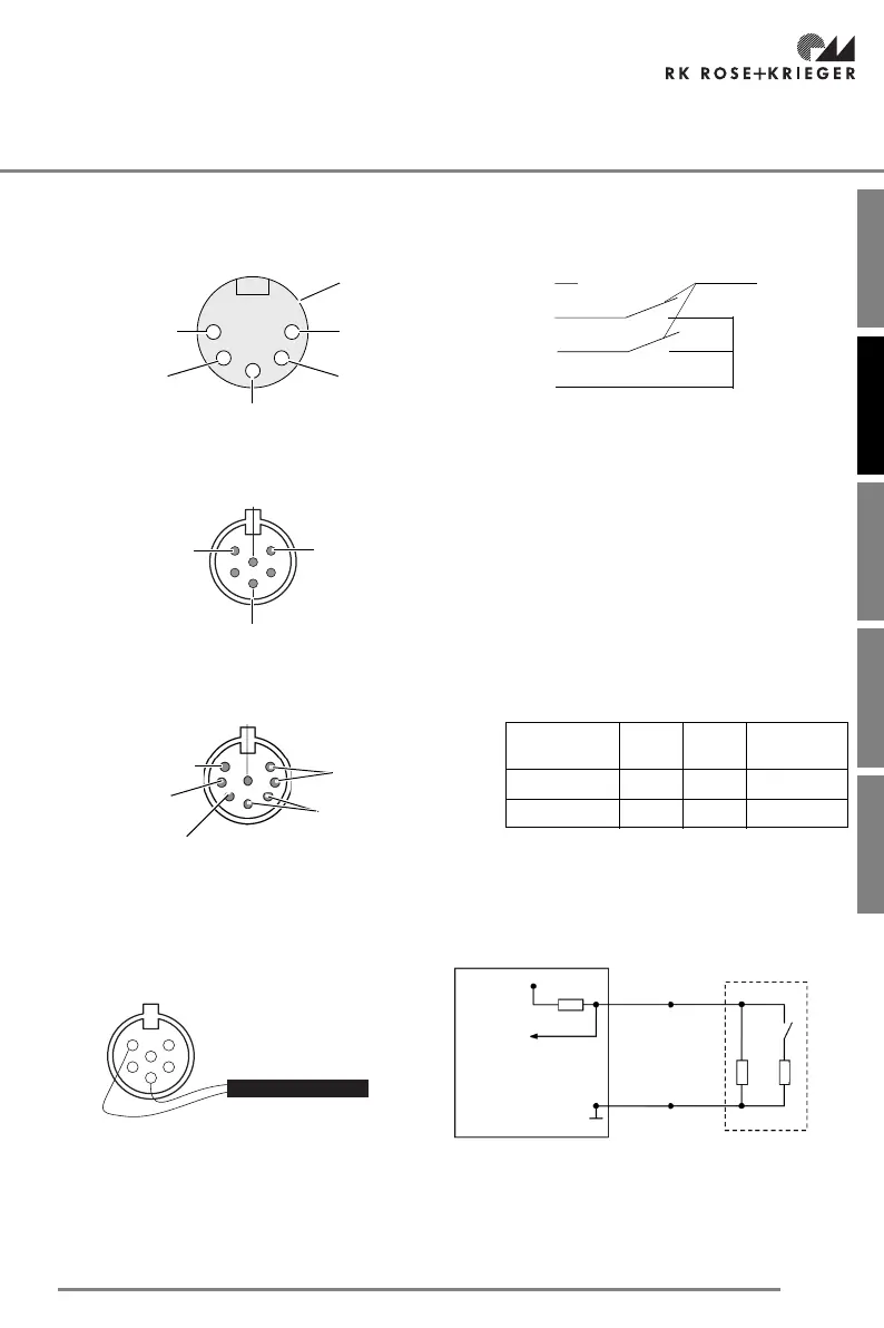
7.2.4 Pin assignment for the plug connections
Pin assignment for the 5-pin plug
Pin assignment for the serial hand switch socket (socket 6)
Pin assignment for the motor socket (sockets 1 and 2)
Switch strip socket terminal assignment (socket 8)
A 6-pin DIN 45322 plug is required to connect the switch strip to the RK MultiControl quadro.
The two ends of the switch strip cable must be soldered onto PIN3 and PIN5 of the plug.
3
2
1
5
4
potential-free
contacts
ground
connected
with pin 2
connected
with pin 4
Drive out
Drive in
Drive in
Drive out
Pin 2
Pin 4
Pin 1
Control example
12 V/20 mA
+12 V
GND
RxD
+5V
TxD
Baud rate: 9600 bauds
Data bits: 7
Stop bit: 1
Parity: odd
Level: TTL
GND
+12V
Motor - Pin 2+4
Motor - Pin 1+7
Hall sensor channel B /
Motor direction of rotation
Option
Pin
1+7
Pin
2+4
Direction
1 + - Drive in
2-+Drive out
limit switch up
Hall sensor channel A /
limit switch down
MultiControl
PIN 5
PIN 3
+5V
3K3
8K2
120
ESB switch strip
RK MultiControl quadro circuit diagram with switch strip.
DIN 45322 plug –
Connection of PIN3 and PIN5 to the switch strip
 Loading...