e/
C
urrent
i
nputs: 0.8 % of
i
nput span
0
A
utotun
i
ng (
A
T)
0:
A
T end or cancel
1:
A
T start or execut
i
on
Turns the autotun
i
ng ON/O
FF
. 0
P
roport
i
onal band
T
C
/RT
D
i
nputs:
1 (0.1) to span
0.1
C
[
F
] resolut
i
on:
W
i
th
i
n 999.9
C
[
F
]
V
oltage/
C
urrent
i
nputs:
0.1 to 100.0 % of
i
nput span
0 (0.0): ON/O
FF
act
i
on
S
et when
P
I,
P
D
or
P
I
D
control
i
s performed.
Heat/
C
ool
P
I
D
act
i
on:
P
roport
i
onal band
sett
i
ng on the heat-s
i
de.
ON/O
FF
act
i
on d
i
fferent
i
al gap:
T
C
/RT
D
i
nputs: 2 (0.2)
C
[
F
]
V
oltage/
C
urrent
i
nputs: 0.2 % of
i
nput span
T
C
/RT
D
i
nputs:
30 (30.0)
V
oltage/
C
urrent
i
nputs: 3.0
Integral t
i
me
1 to 3600 seconds
(0 second:
P
D
act
i
on)
S
et the t
i
me of
i
ntegral act
i
on to el
i
m
i
nate the
offset occurr
i
ng
i
n proport
i
onal control.
240
D
er
i
vat
i
ve t
i
me 1 to 3600 seconds
(0 second:
P
I act
i
on)
S
et the t
i
me of der
i
vat
i
ve act
i
on to
i
mprove
control stab
i
l
i
ty by prepar
i
ng for output
changes.
60
A
nt
i
-reset w
i
ndup
(
A
RW)
1 to 100 % of heat-s
i
de proport
i
onal
band (0 %: Integral act
i
on O
FF
)
Overshoot
i
ng and undershoot
i
ng are
restr
i
cted by the
i
ntegral effect.
100
Heat-s
i
de
proport
i
on
i
ng
cycle
1 to 100 seconds
(Not d
i
splayed
i
f the control output
i
s
current output.)
S
et control output cycle.
Heat/
C
ool
P
I
D
act
i
on:
Heat-s
i
de proport
i
on
i
ng cycle
R
elay contact output: 20
V
oltage pulse output/
Tr
i
gger output for tr
i
ac
dr
i
v
i
ng: 2
C
ool-s
i
de
proport
i
onal band
1 to 1000 % of heat-s
i
de
proport
i
onal band
S
et cool-s
i
de proport
i
onal band when
Heat/
C
ool
P
I
D
act
i
on.
100
D
eadband T
C
/RT
D
i
nputs:
10 to +10
C
[
F
] or
10.0 to +10.0
C
[
F
]
V
oltage/
C
urrent
i
nputs:
10.0 to +10.0 % of
i
nput span
S
et control act
i
on deadband between
heat-s
i
de and cool-s
i
de proport
i
onal bands.
M
i
nus (
) sett
i
ng results
i
n overlap.
0 or 0.0
C
ool-s
i
de
proport
i
on
i
ng
cycle
1 to 100 seconds
(Not d
i
splayed
i
f the control output
i
s
current output.)
S
et control cool-s
i
de output cycle for
Heat/
C
ool
P
I
D
act
i
on.
Relay contact output: 20
V
oltage pulse output: 2
S
et data lock
(L
C
K
)
0100: No set data locked
(
A
ll parameters changeable)
0101:
S
et data locked
(
A
ll parameters locked)
0110: Only the set value (
SV
)
i
s
changeable w
i
th the set data
locked
P
erforms set data change enable/d
i
sable. 0100
1
H
eater
B
reak Alarm (
HB
A) f
un
cti
on
The H
BA
funct
i
on mon
i
tors the current flow
i
ng through the load by a
ded
i
cated current transformer (
C
T), compares the measured value w
i
th
the H
BA
set value, and detects a fault
i
n the heat
i
ng c
i
rcu
i
t.
Lo
w
o
r
N
o
c
u
rre
n
t fl
o
w
(
H
eater
b
reak, malf
un
cti
on
o
f t
h
e c
on
tr
o
l
d
evice, etc.)
:
When the control output
i
s ON and the current transformer
i
nput value
i
s
equal to or less than the heater break determ
i
nat
i
on po
i
nt for the preset
number of consecut
i
ve sampl
i
ng cycle, an alarm
i
s act
i
vated.
Over c
u
rre
n
t
o
r s
ho
rt-circ
u
it
:
When the control output
i
s O
FF
and the current transformer
i
nput value
i
s
equal to or greater than the heater break determ
i
nat
i
on po
i
nt for the
preset number of consecut
i
ve sampl
i
ng cycle, an alarm
i
s act
i
vated.
P
recaut
i
on for H
BA
sett
i
ng:
D
i
splayed only for when H
BA
i
s selected as
A
larm 2.
H
BA
i
s not ava
i
lable on a current output.
S
et the set value to approx
i
mately 85 % of the max
i
mum read
i
ng of the
C
T
i
nput.
S
et the set value to a sl
i
ghtly smaller value to prevent a false alarm
i
f
the power supply may become unstable.
When more than one heater
i
s connected
i
n parallel,
i
t may be
necessary to
i
ncrease the H
BA
set value to detect a s
i
ngle heater
fa
i
lure.
When the current transformer
i
s not connected or the H
BA
set value
i
s
set to “0.0,” the H
BA
i
s turned on.
2
C
on
tr
o
l
Loop
B
reak Alarm (
L
B
A) f
un
cti
on
The L
BA
funct
i
on
i
s used to detect a load (heater) break or a fa
i
lure
i
n the
external actuator (power controller, magnet relay, etc.), or a fa
i
lure
i
n the
control loop caused by an
i
nput (sensor) break. The L
BA
funct
i
on
i
s
act
i
vated when control output reaches 0 % or 100 %. L
BA
mon
i
tors
var
i
at
i
on of the measured value (
PV
) for the length of L
BA
t
i
me. When
the L
BA
t
i
me has elapsed and the
PV
i
s st
i
ll w
i
th
i
n the alarm
determ
i
nat
i
on range, the L
BA
w
i
ll be ON.
P
recaut
i
on for L
BA
sett
i
ng:
D
i
splayed only for when L
BA
i
s selected as
A
larm 1 or
A
larm 2.
No L
BA
funct
i
on can be used at Heat/
C
ool
P
I
D
control act
i
on.
The L
BA
funct
i
on can not be act
i
vated when
A
T funct
i
on
i
s turned on.
The L
BA
funct
i
on
i
s act
i
vated when control output reaches 0 % or
100 %. The t
i
me requ
i
red for the L
BA
output to turn on
i
ncludes both
the t
i
me from the
i
n
i
t
i
al occurrence of loop fa
i
lure and the L
BA
sett
i
ng
t
i
me. Recommended sett
i
ng for L
BA
i
s for the set value of the L
BA
to
be tw
i
ce the value of the
i
ntegral t
i
me (I).
If L
BA
sett
i
ng t
i
me does not match the controlled object requ
i
rements,
the L
BA
sell
i
ng t
i
me should be lengthened.
If sett
i
ng t
i
me
i
s not correct, the L
BA
w
i
ll malfunct
i
on by turn
i
ng on or
off at
i
nappropr
i
ate t
i
mes or not turn
i
ng on at all.
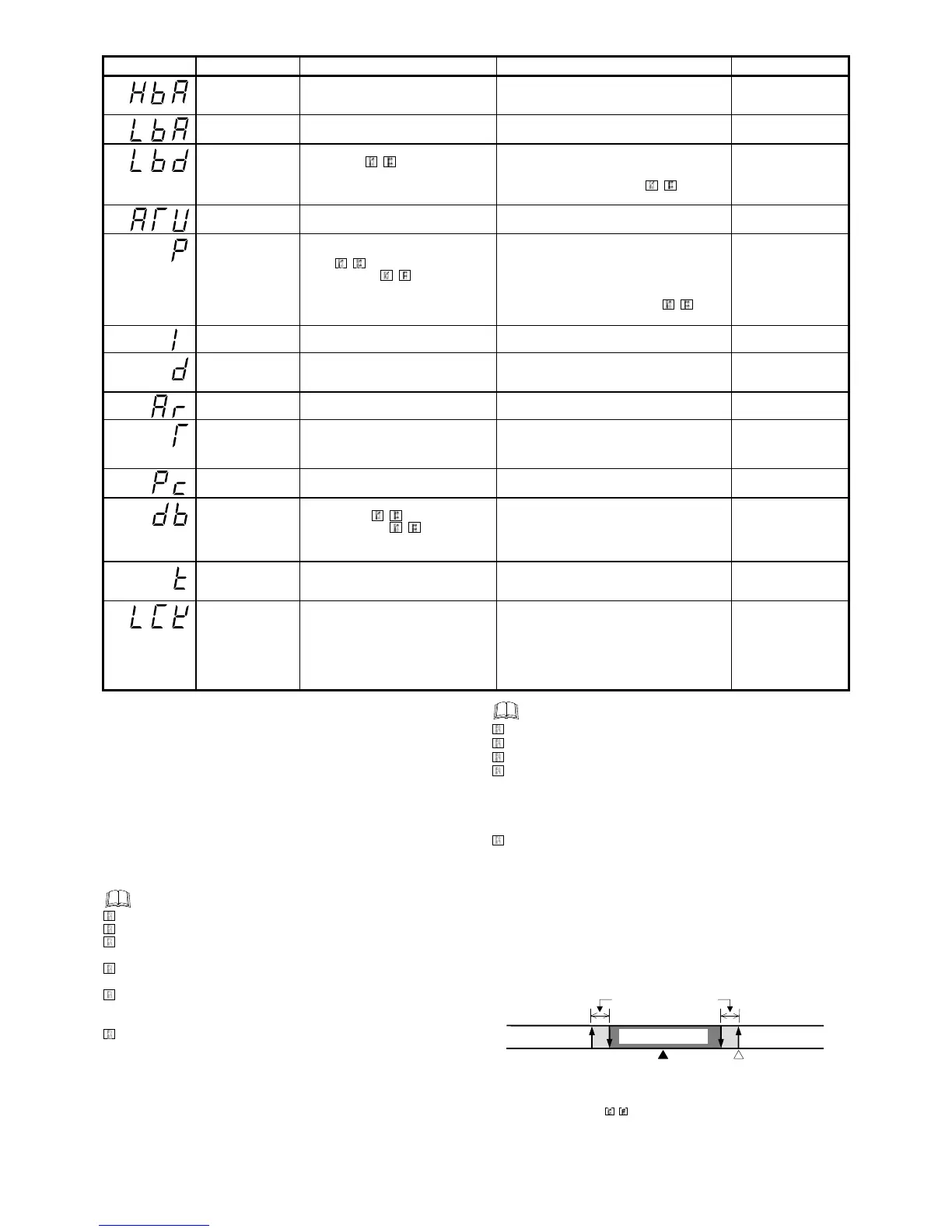
3
L
B
A
D
ea
db
a
nd
f
un
cti
on
The L
BA
may malfunct
i
on due to external d
i
sturbances. To prevent
malfunct
i
on
i
ng due to external d
i
sturbance, L
BA
deadband (L
B
D
) sets a
neutral zone
i
n wh
i
ch L
BA
i
s not act
i
vated. When the measured value
(
PV
)
i
s w
i
th
i
n the L
B
D
area, L
BA
w
i
ll not be act
i
vated. If the L
B
D
sett
i
ng
i
s not correct, the L
BA
w
i
ll not work correctly.
* T
C
and RT
D
i
nputs: 0.8
C
[
F
] (f
i
xed)
V
oltage/
C
urrent
i
nputs: 0.8 % of
i
nput span (f
i
xed)
A
:
D
ur
i
ng temperature r
i
se:
A
larm area
D
ur
i
ng temperature fall: Non-alarm area

 Loading...


