7
7
.
3
I
n
iti
a
l
S
e
tti
ng
M
e
nu
D
i
s
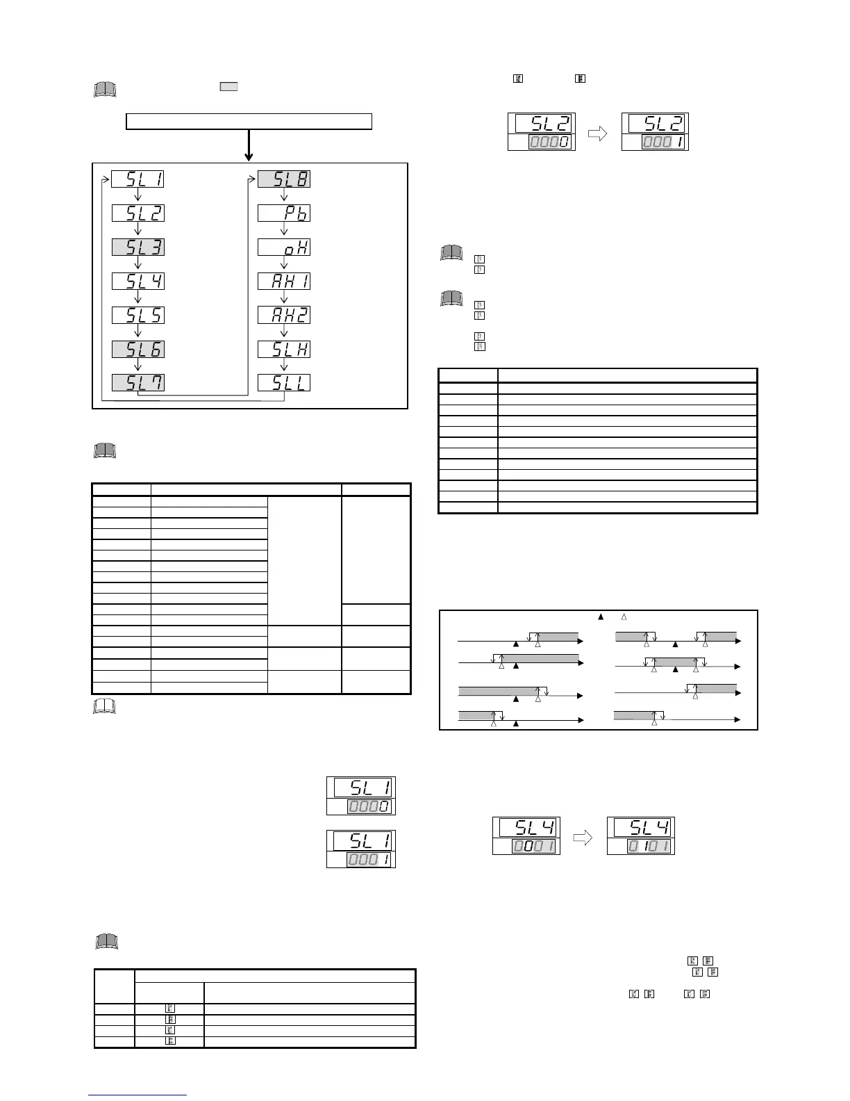
play flowcharts
i
n In
i
t
i
al
i
zat
i
on mode are shown
i
n the follow
i
ng.
D
o
no
t
c
h
a
ng
e t
o
t
h
e secti
on
p
arameters a
nd
a
n
y
p
arameter i
n
t
h
e I
n
itiali
z
ati
on
m
od
e
w
h
ic
h
is
no
t
d
escri
b
e
d
i
n
t
h
e i
n
itial setti
ng
me
nu
b
el
o
w
. It may res
u
lt i
n
malf
un
cti
on
o
r fail
u
re
o
f t
h
e i
n
str
u
me
n
t.
7
.
4
I
npu
t
T
y
p
e
S
e
l
ec
ti
on
(
S
L
1
)
W
h
e
n
a
n
y
p
arameter setti
ng
is c
h
a
ng
e
d
i
n
t
h
e I
n
itiali
z
ati
on
m
od
e,
c
h
eck all
p
arameter set val
u
es i
n
SV
setti
ng
m
od
e a
nd
P
arameter
setti
ng
m
od
e.
F
actory set value var
i
es depend
i
ng on the
i
nput type.
S
et val
u
e I
npu
t ty
p
e
H
ar
d
w
are
0000
K
Thermocouple
(T
C
)
A
0001 J
0010 L
0011
E
0100 N
0111 R
1000
S
1001
B
1010 W5Re/W26Re
1011
P
L II
0101 T
B
0110 U
1100
P
t100 (JI
S
/I
E
C
)
RT
D
C
1101 J
P
t100 (JI
S
)
1110
0 to 5
V
DC
V
oltage
D
1111
1 to 5
V
DC
1110
0 to 20 m
A
DC
C
urrent
E
1111
4 to 20 m
A
DC
C
onduct sett
i
ng so as to meet the
i
nstrument spec
i
f
i
cat
i
on (
i
nput type).
S
ett
i
ng change between d
i
fferent symbols may cause malfunct
i
on,
but the sett
i
ng can be changed when hardware types have the same
symbol. However, when the sett
i
ng
i
s changed, always reset “
S
LH”
and “
S
LL” (Refer to page 8).
C
h
a
ng
e
S
etti
ng
s
E
xam
p
le
:
C
h
a
ng
e t
h
e i
npu
t ty
p
e fr
o
m “
K
” t
o
“J”
1
.
P
ress the
SE
T key. The d
i
splay w
i
ll go to
S
L1.
2.
P
ress the U
P
key to change the number to 1.
3.
P
ress the
SE
T key to store the new set value.
The d
i
splay goes to the next parameter.
7
.
5
T
e
m
p
e
r
a
t
u
r
e
U
n
it
a
nd
C
oo
li
ng
T
y
p
e
S
e
l
ec
ti
on
(
S
L
2
)
I
n
a
pp
r
op
riate setti
ng
s may res
u
lt i
n
malf
un
cti
on
.
C
on
tr
o
l ty
p
e
b
et
w
ee
n
H
eat O
n
ly a
nd
H
eat/
C
oo
l ca
nno
t
b
e c
h
a
ng
e
d
b
y t
h
is
p
arameter.
F
actory set value var
i
es depend
i
ng on the
i
nstrument spec
i
f
i
cat
i
on.
S
et
val
u
e
D
escri
p
ti
on
T
em
p
erat
u
re
un
it
C
oo
li
ng
ty
p
e selecti
on
0000
C
A
i
r cool
i
ng (
A
type) or Heat only type (
F
,
D
type)
0001
F
A
i
r cool
i
ng (
A
type) or Heat only type (
F
,
D
type)
0010
C
Water cool
i
ng (W type)
0011
F
Water cool
i
ng (W type)
C
h
a
ng
e
S
etti
ng
s
E
xam
p
le
:
C
h
a
ng
e t
h
e tem
p
erat
u
re
un
it
o
f t
h
e
H
eat
on
ly ty
p
e
fr
o
m “
C
(0000)” t
o
“
F
(0001)”
1.
P
ress the
SE
T key unt
i
l
S
L2
i
s d
i
splayed.
2.
P
ress the U
P
key to change the number to 1.
SV
PV
SV
PV
3.
P
ress the
SE
T key to store the new set value. The d
i
splay goes to the
next parameter.
7
.
6
Al
a
rm
1
[A
L
M
1
]
T
y
p
e
S
e
l
ec
ti
on
(
S
L
4
)
Al
a
rm
2
[A
L
M
2
]
T
y
p
e
S
e
l
ec
ti
on
(
S
L
5
)
If the alarm funct
i
on
i
s not prov
i
ded w
i
th the
i
nstrument when sh
i
pped from the
factory, no alarm output
i
s ava
i
lable by chang
i
ng
S
L4 and/or
S
L5.
SL
4 is set t
o
0000 i
n
t
h
e f
o
ll
o
w
i
ng
cases.
W
h
e
n
t
h
e i
n
str
u
me
n
t
do
es
no
t
h
ave A
L
M1
ou
t
pu
t
W
h
e
n
C
on
tr
o
l
Loop
B
reak Alarm (
L
B
A) is
p
r
o
vi
d
e
d
a
nd
assi
gn
e
d
t
o
A
L
M1
SL
5 is set t
o
0000 i
n
t
h
e f
o
ll
o
w
i
ng
cases.
W
h
e
n
t
h
e i
n
str
u
me
n
t
do
es
no
t
h
ave A
L
M2
ou
t
pu
t
W
h
e
n
C
on
tr
o
l
Loop
B
reak Alarm (
L
B
A) is
p
r
o
vi
d
e
d
a
nd
assi
gn
e
d
t
o
A
L
M2
W
h
e
n
t
h
e
SV
alarm is
p
r
o
vi
d
e
d
a
nd
assi
gn
e
d
t
o
A
L
M2
W
h
e
n
t
h
e
H
eater
B
reak Alarm (
HB
A) is
p
r
o
vi
d
e
d
F
a
ctory set value var
i
es depend
i
ng on the
i
nstrument spec
i
f
i
cat
i
on.
S
et val
u
e
D
etails
o
f setti
ng
0000 No alarm
0001
D
ev
i
at
i
on h
i
gh alarm
0101
D
ev
i
at
i
on low alarm
0010
D
ev
i
at
i
on h
i
gh/low alarm
0110
B
and alarm
0011
P
rocess h
i
gh alarm
0111
P
rocess low alarm
1001
D
ev
i
at
i
on h
i
gh alarm w
i
th hold act
i
on *
1101
D
ev
i
at
i
on low alarm w
i
th hold act
i
on *
1010
D
ev
i
at
i
on h
i
gh/low alarm w
i
th hold act
i
on *
1011
P
rocess h
i
gh alarm w
i
th hold act
i
on *
1111
P
rocess low alarm w
i
th hold act
i
on *
* Hold act
i
on:
When Hold act
i
on
i
s ON, the alarm act
i
on
i
s suppressed at start-up or the
control set value change unt
i
l the measured value enters the non-alarm range.
Alarm acti
on
ty
p
e
B
oth of the
A
larm 1 and
A
larm 2 outputs of th
i
s
i
nstrument are turned on when
burnout occurs regardless of any of the follow
i
ng act
i
ons taken (H
i
gh alarm, low
alarm, etc.). In add
i
t
i
on, when used for any purposes other than these alarms
(event, etc.), spec
i
fy the Z-124 spec
i
f
i
cat
i
on (not to be forc
i
bly turned on).
( :
SV
:
A
l
arm set value
☆
:
A
larm d
i
fferent
i
al gap)
D
e
v
i
at
i
on h
i
gh alarm
D
ev
i
at
i
on h
i
gh/low alarm
D
ev
i
at
i
on low alarm
(
A
larm set value
i
s less than 0.)
(
A
larm set value
i
s less than 0.)
Lo
w H
i
gh
O
FF ON
PV
OFF ON
PV
Low H
i
gh
OFF
ON
PV
Low
H
i
gh
OFF ON
PV
Low H
i
gh
OFF ON
PV
Low
H
i
gh
(
A
larm set value
i
s greater than 0.)
(
A
larm set value
i
s greater than 0.)
ON OFF
PV
B
and alarm
P
rocess low alarm
P
rocess h
i
gh alarm
OFF OFF ON
PV
Low
H
i
gh
Low H
i
gh
OFF ON
PV
Low H
i
gh
ON
☆
☆
☆
☆
☆☆
☆
☆
☆
☆
C
h
a
ng
e
S
etti
ng
s
E
xam
p
le
:
C
h
a
ng
e t
h
e A
L
M1 ty
p
e fr
o
m “
D
eviati
on
h
i
gh
alarm (0001)” t
o
“
D
eviati
on
l
o
w
alarm (0101)”
1.
P
ress the
SE
T key three t
i
mes at
S
L1 unt
i
l
S
L4
i
s d
i
splayed.
2.
P
ress the sh
i
ft key to h
i
gh-l
i
ght the hundreds d
i
g
i
t.
3.
P
ress the U
P
key to change the number to 1.
4.
P
ress the
SE
T key to store the new set value. The d
i
splay goes to the
next parameter.
7
.
7
PV
b
i
as
(
P
b
)
The value set
i
n the
PV
b
i
as
i
s added to the
i
nput value (actual measured
value) to correct the
i
nput value. The
PV
b
i
as
i
s used to correct the
i
nd
i
v
i
dual
var
i
at
i
ons
i
n the sensors or when there
i
s d
i
fference between the measured
values (
PV
) of other
i
nstruments.
S
ett
i
ng range: T
C
/RT
D
i
nputs:
1999 to +9999
C
[
F
] or
199.9 to +999.9
C
[
F
]
V
oltage/
C
urrent
i
nputs:
199.9 to +200.0 %
F
actory set value: T
C
/RT
D
i
nputs: 0
C
[
F
] or 0.0
C
[
F
]
V
oltage/
C
urrent
i
nputs: 0.0 %
C
o
nt
i
nued on the next page.
In
put type select
i
on
SV
PV
SV
PV
P
ress the sh
i
ft key wh
i
le press
i
ng
the
SE
T key for 5 seconds w
i
th
the unlocked.
PV
/
SV
d
i
splay mode or
P
arameter sett
i
ng mode
In
put type select
i
on
SE
T k
ey
(
S
L1)
SE
T key
SE
T key

 Loading...


