6
5
.
3
C
h
a
ng
i
ng
P
a
r
a
m
e
t
e
r
S
e
tti
ng
s
P
r
ocedures to change parameter sett
i
ngs are shown below.
C
h
a
ng
e
t
h
e set val
u
e (
SV
)
C
h
a
ng
e
t
h
e set val
u
e (
SV
) fr
o
m 0
C
t
o
200
C
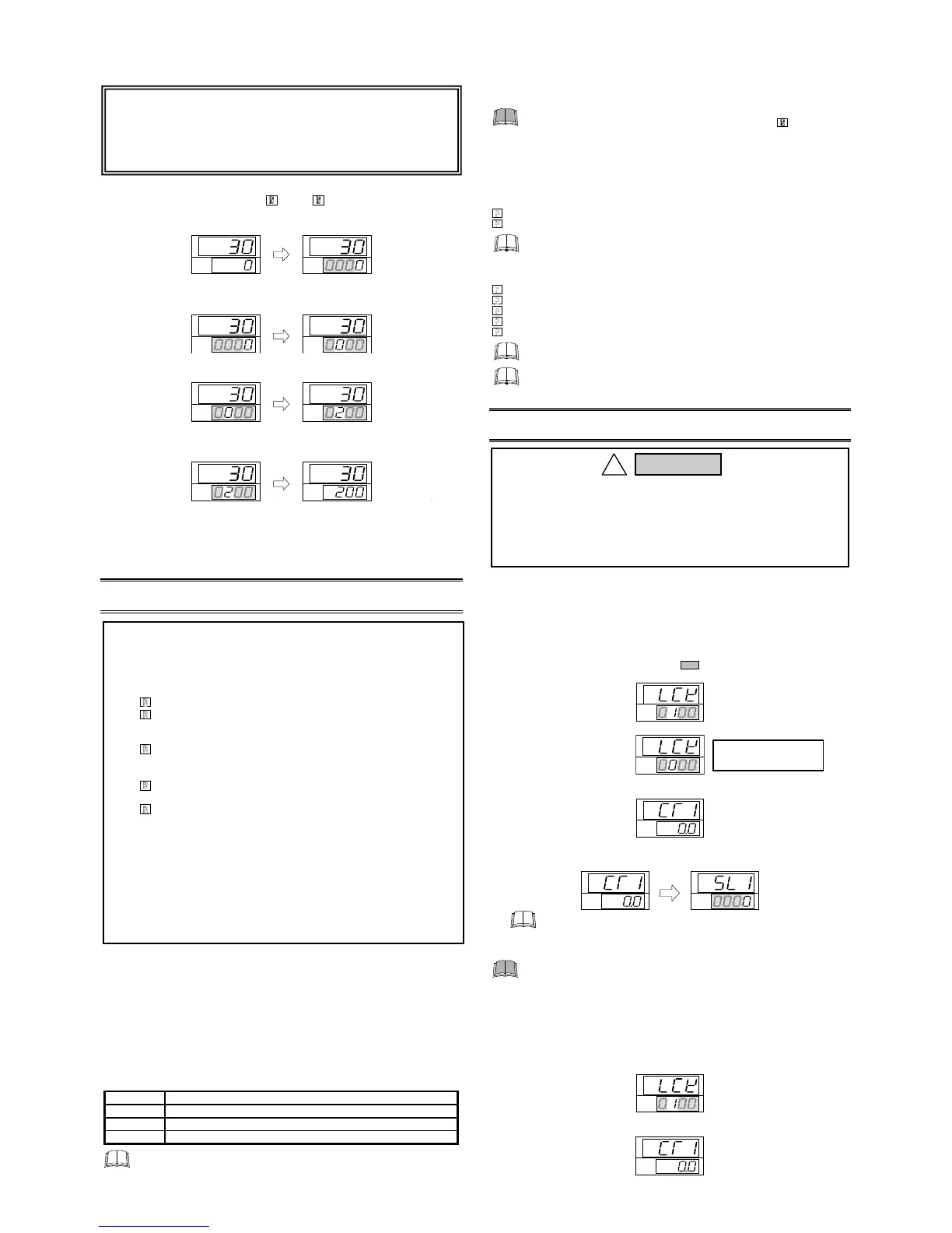
1.
S
elect t
h
e
SV
setti
ng
m
od
e
P
ress the
SE
T key at
PV
/
SV
mon
i
tor screen unt
i
l
SV
sett
i
ng screen
i
s d
i
splayed.
SV
PV
SV
PV
2.
Sh
ift t
h
e
h
i
gh
-li
gh
te
d
d
i
g
it
P
ress the sh
i
ft key to h
i
gh-l
i
ght the hundreds d
i
g
i
t.
The h
i
gh-l
i
ghted d
i
g
i
t
i
nd
i
cates wh
i
ch d
i
g
i
t can be set.
SV
PV
SV
PV
3.
C
h
a
ng
e t
h
e set val
u
e
P
ress the U
P
key to change the number to 2.
SV
PV
SV
PV
4.
S
t
o
re t
h
e set val
u
e
P
ress the
SE
T key to store the new set value. The d
i
splay returns to the
PV
/
SV
mon
i
tor screen.
SV
PV
SV
PV
C
h
a
ng
e
p
arameters
o
t
h
er t
h
a
n
t
h
e set val
u
e (
SV
)
The chang
i
ng procedures are the same as those of example 2 to 4
i
n the
above
"
C
h
a
ng
e t
h
e
set val
u
e (
SV
)
"
.
P
ress
i
ng the
SE
T key after the sett
i
ng
end sh
i
fts to the next parameter. When no parameter sett
i
ng
i
s requ
i
red, return
the
i
nstrument to the
PV
/
SV
d
i
splay mode.
6
. O
PE
R
A
T
IO
N
6
.
1
O
p
e
r
a
ti
ng
P
r
eca
u
ti
on
s
(1)
A
ll mount
i
ng and w
i
r
i
ng must be completed before the power
i
s turned on.
(2) The sett
i
ngs for the
SV
and all parameters should be appropr
i
ate for the
controlled object.
(3)
A
power supply sw
i
tch
i
s not furn
i
shed w
i
th th
i
s
i
nstrument. It
i
s ready to
operate as soon as the power
i
s turned on.
6
.
2
S
e
t
D
a
t
a
Lo
ck
(
L
CK
)
Fun
c
ti
on
The set data lock restr
i
cts parameter sett
i
ng changes by key operat
i
on. Th
i
s
funct
i
on prevents the operator from mak
i
ng errors dur
i
ng operat
i
on.
S
et val
u
e
P
arameters
w
h
ic
h
ca
n
b
e c
h
a
ng
e
d
0100
A
ll parameters [
F
actory set value]
0101 No parameters [
A
ll Locked]
0110
SV
P
arameters protected by
S
et
D
ata Lock funct
i
on are st
i
ll d
i
splayed for
mon
i
tor
i
ng.
6
.
3
A
u
t
o
t
un
i
ng
(A
T
)
Fun
c
ti
on
A
utotun
i
ng (
A
T) automat
i
cally measures, calculates and sets the opt
i
mum
P
I
D
and L
BA
constants. The follow
i
ng cond
i
t
i
ons are necessary to carry out
autotun
i
ng and the cond
i
t
i
ons wh
i
ch w
i
ll cause the autotun
i
ng to stop.
C
a
u
ti
on
f
o
r
u
si
ng
t
h
e A
u
t
o
t
un
i
ng
(A
T
)
W
h
e
n
a tem
p
erat
u
re c
h
a
ng
e (
U
P
a
nd
/
o
r
D
o
w
n
) is 1
C
o
r less
p
er
mi
nu
te
du
ri
ng
A
u
t
o
t
un
i
ng
, A
u
t
o
t
un
i
ng
may
b
e ca
n
celle
d
b
ef
o
re
calc
u
lati
ng
P
I
D
val
u
es. I
n
t
h
at case, a
d
j
u
st t
h
e
P
I
D
val
u
es ma
nu
ally. It
is
po
ssi
b
le t
o
h
a
pp
e
n
w
h
e
n
t
h
e set val
u
e is ar
ound
t
h
e am
b
ie
n
t
tem
p
erat
u
re
o
r is cl
o
se t
o
t
h
e maxim
u
m tem
p
erat
u
re ac
h
ieve
d
b
y t
h
e
l
o
a
d
.
R
e
qu
ireme
n
ts f
o
r A
T
start
S
tart the autotun
i
ng when all follow
i
ng cond
i
t
i
ons are sat
i
sf
i
ed:
P
r
i
or to start
i
ng the
A
T funct
i
on, end all the parameter sett
i
ngs other than
P
I
D
and L
BA
.
C
onf
i
rm the L
C
K
funct
i
on has not been engaged.
When the autotun
i
ng
i
s f
i
n
i
shed, the controller w
i
ll automat
i
cally returns to
P
I
D
control.
R
e
qu
ireme
n
ts f
o
r A
T
ca
n
cellati
on
The autotun
i
ng
i
s canceled
i
f any of the follow
i
ng cond
i
t
i
ons ex
i
st.
When the set value (
SV
)
i
s changed.
When the
PV
b
i
as value
i
s changed.
When the
PV
becomes abnormal due to burnout.
When the power
i
s turned off.
When power fa
i
lure longer than 20 ms occurs.
I
f the
A
T
i
s canceled, the controller
i
mmed
i
ately changes to
P
I
D
control. The
P
I
D
values w
i
ll be the same as before
A
T was act
i
vated.
When
A
T
i
s completed, the controller
i
mmed
i
ately changes to
P
I
D
control. If
the control system does not allow the
A
T cycl
i
ng process, set each
P
I
D
constant manually to meet the needs of the appl
i
cat
i
on.
7
. I
N
I
T
IA
L
SE
TT
I
N
G
7
.
1
G
o
t
o
I
n
iti
a
li
z
a
ti
on
M
od
e
1
.
Turn on the power to th
i
s controller. The
i
nstrument goes to the
PV
/
SV
d
i
splay after conf
i
rm
i
ng
i
nput type symbol and
i
nput range.
2.
P
ress and hold the
SE
T key for 5 seconds to go to the
P
arameter sett
i
ng
mode from the
PV
/
SV
d
i
splay.
3.
P
ress the
SE
T key unt
i
l “L
C
K
” (
S
et
D
ata Lock d
i
splay) w
i
ll be d
i
splayed.
4.
The h
i
gh-l
i
ghted d
i
g
i
t
i
nd
i
cates wh
i
ch d
i
g
i
t can be set.
P
ress sh
i
ft key to
h
i
gh-l
i
ght the hundreds d
i
g
i
t. (The sect
i
on
i
n each
i
mage of the
controller shows the d
i
g
i
ts wh
i
ch are not h
i
gh-l
i
ghted.)
SV
PV
5.
P
ress the
D
OWN key to change 1 to 0.
SV
PV
6.
P
ress the
SE
T key to store the new set value. The d
i
splay goes to the
next parameter, and the In
i
t
i
al
i
zat
i
on mode
i
s unlocked.
SV
PV
7.
P
ress the sh
i
ft key for 5 seconds wh
i
le press
i
ng the
SE
T key to go to the
In
i
t
i
al
i
zat
i
on mode. When the controller goes to the In
i
t
i
al
i
zat
i
on mode,
“
S
L1” w
i
ll be d
i
splayed.
SV
PV
SV
PV
If the control
i
s set to the
i
n
i
t
i
al set mode, all outputs are turned O
FF
.
7
.
2
E
x
it I
n
iti
a
li
z
a
ti
on
M
od
e
W
h
e
n
a
n
y
p
arameter setti
ng
is c
h
a
ng
e
d
i
n
t
h
e I
n
itiali
z
ati
on
m
od
e,
c
h
eck all
p
arameter set val
u
es i
n
SV
setti
ng
m
od
e a
nd
P
arameter
setti
ng
m
od
e.
1.
P
ress the sh
i
ft key for 5 seconds wh
i
le press
i
ng the
SE
T key from any
d
i
splay
i
n the In
i
t
i
al
i
zat
i
on mode. The controller goes back to the operat
i
on
mode and the
PV
/
SV
d
i
splay w
i
ll be d
i
splayed.
2.
P
ress and hold the
SE
T key for 5 seconds
i
n the
PV
/
SV
d
i
splay.
3.
P
ress the
SE
T key unt
i
l “L
C
K
” (
S
et
D
ata Lock d
i
splay) w
i
ll be d
i
splayed.
4.
The h
i
gh-l
i
ghted d
i
g
i
t
i
nd
i
cates wh
i
ch d
i
g
i
t can be set.
P
ress sh
i
ft key to
h
i
gh-l
i
ght the hundreds d
i
g
i
t.
SV
PV
5.
P
ress the
SE
T key to store the new set value. The d
i
splay goes to the
next parameter, and the In
i
t
i
al
i
zat
i
on mode
i
s locked.
To
st
o
re a
n
e
w
val
u
e f
o
r t
h
e
p
arameter, al
w
ays
p
ress t
h
e
SET
key.
The d
i
splay changes to the next parameter and the new value w
i
ll be stored.
A
new value w
i
ll not be stored w
i
thout press
i
ng
SE
T key after the new
value
i
s d
i
splayed on the d
i
splay.
A
fter a new value has been d
i
splayed by us
i
ng the U
P
and
D
OWN keys,
the
SE
T key must be pressed w
i
th
i
n 1 m
i
nute, or the new value
i
s not
stored and the d
i
splay w
i
ll return to the
PV
/
SV
mon
i
tor screen.
PV
/
SV
m
on
i
tor d
i
splay
(
PV
/
SV
d
i
splay mode)
SV
sett
i
ng d
i
splay
(
SV
sett
i
ng mode)
PV
/
SV
mon
i
tor d
i
splay
P
arameters i
n
t
h
e I
n
itiali
z
ati
on
m
od
e s
hou
l
d
b
e set acc
o
r
d
i
ng
t
o
t
h
e
a
pp
licati
on
b
ef
o
re setti
ng
a
n
y
p
arameter relate
d
t
o
op
erati
on
. O
n
ce
t
h
e
P
arameters i
n
t
h
e I
n
itiali
z
ati
on
m
od
e are set c
o
rrectly,
no
f
u
rt
h
er
c
h
a
ng
es
n
ee
d
t
o
b
e ma
d
e t
o
p
arameters f
o
r t
h
e same a
pp
licati
on
und
er
no
rmal c
ond
iti
on
s. If t
h
ey are c
h
a
ng
e
d
unn
ecessarily, it may
res
u
lt i
n
malf
un
cti
on
o
r fail
u
re
o
f t
h
e i
n
str
u
me
n
t.
RKC
w
ill
no
t
b
ear
a
n
y res
pon
si
b
ility f
o
r malf
un
cti
on
o
r fail
u
re as a res
u
lt
o
f im
p
r
op
er
c
h
a
ng
es i
n
t
h
e I
n
itiali
z
ati
on
m
od
e.
S
et data lock funct
i
on d
i
splay
S
et value
0: In
i
t
i
al
i
zat
i
on mode unlocked
1: In
i
t
i
al
i
zat
i
on mode locked
C
T1
i
nput value d
i
splay
The parameter d
i
splayed var
i
es
on the
i
nstrument spec
i
f
i
cat
i
on.
In
i
t
i
al
i
ze code
select
i
on d
i
splay
of
i
n
i
t
i
al
i
zat
i
on
mode
C
T1
i
nput value
d
i
splay
C
A
U
T
IO
N
S
All m
oun
ti
ng
a
nd
w
iri
ng
m
u
st
b
e c
o
m
p
lete
d
b
ef
o
re t
h
e
po
w
er is t
u
r
n
e
d
on
. If t
h
e i
npu
t si
gn
al
w
iri
ng
is
d
isc
onn
ecte
d
o
r s
ho
rt-circ
u
ite
d
(
R
T
D
i
npu
t
on
ly), t
h
e i
n
str
u
me
n
t
d
etermi
n
es t
h
at
bu
r
nou
t
h
as
o
cc
u
rre
d
.
D
i
s
plays:
Upscale: Thermocouple
i
nput, RT
D
i
nput (when
i
nput break)
D
ownscale: Thermocouple
i
nput (spec
i
fy when order
i
ng),
RT
D
i
nput (when short-c
i
rcu
i
ted),
V
oltage
i
nput (1 to 5
V
DC
),
C
urrent
i
nput (4 to 20 m
A
DC
)
F
or the voltage (0 to 5
V
DC
) or current (0 to 20 m
A
DC
)
i
nput, the
d
i
splay becomes
i
ndef
i
n
i
te (d
i
splay of about zero value).
Outputs:
C
ontrol output: O
FF
(Heat/
C
ool control: the control output on
both heat-s
i
de and cool-s
i
de
i
s turned off)
A
larm output:
B
oth of the
A
larm 1 and
A
larm 2 outputs of th
i
s
i
nstrument are turned on when burnout occurs
regardless of any of the follow
i
ng act
i
ons taken. (H
i
gh
alarm, low alarm, etc.) In add
i
t
i
on, when used for any
purposes other than these alarms (event, etc.), spec
i
fy
the Z-124 spec
i
f
i
cat
i
on (not to be forc
i
bly turned on).
A
po
w
er fail
u
re
o
f 20 ms
o
r less
w
ill
no
t affect t
h
e c
on
tr
o
l acti
on
.
W
h
e
n
a
po
w
er fail
u
re
o
f m
o
re t
h
a
n
20 ms
o
cc
u
rs, t
h
e i
n
str
u
me
n
t
ass
u
mes t
h
at t
h
e
po
w
er
h
as
b
ee
n
t
u
r
n
e
d
o
ff. W
h
e
n
po
w
er ret
u
r
n
s,
t
h
e c
on
tr
o
ller
w
ill retai
n
t
h
e c
ond
iti
on
s t
h
at existe
d
p
ri
o
r t
o
s
hu
t
do
w
n
.
Th
e alarm
ho
l
d
acti
on
is activate
d
w
h
e
n
no
t
on
ly t
h
e
po
w
er is
t
u
r
n
e
d
on
,
bu
t als
o
t
h
e
SV
is c
h
a
ng
e
d
.
S
et data lock funct
i
on d
i
splay
C
T1
i
nput value d
i
splay
The parameter d
i
splayed var
i
es on
the
i
nstrument spec
i
f
i
cat
i
on.
SV
PV
WA
RN
I
N
G
!

 Loading...


