4
4
.
P
A
R
T
S
D
ES
CR
I
P
T
IO
N
(
1)
C
100
PV
SV
(2)
(3)
(4)
(5) (6) (7)
PV
SV
(3)
C
410
(1)
(3)
(4) (5) (6) (7)
PV
SV
(1)
(4)
(5)
(6)
(7)
C
400
(2)
PV
SV
(1)
(3)
(2)
(4) (5) (6) (7)
C
700,
C
900
A
L
M1
ALM2
OUT
AT
R
EX
-
C
100
SET
SET
SET
REX-
C
400
ALM1
ALM2
OUT1
AT
OUT2
(3)
REX-
C
410
ALM1
ALM2
OUT1
OUT2
AT
REX-
C
900
SET
(2)
ALM1
ALM2
OUT1
AT
OUT2
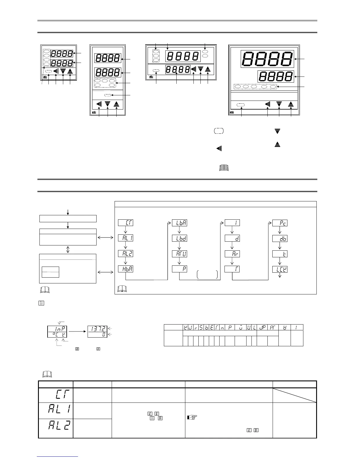
5
.
SE
TT
I
N
G
5
.
1
O
p
e
r
a
ti
on
M
e
nu
I
npu
t t
y
p
e a
nd
i
npu
t ra
ng
e
d
is
p
lay
Th
i
s
i
nstrum
ent
i
mmed
i
ately conf
i
rms the
i
nput type symbol and
i
nput range follow
i
ng power ON.
E
xample: When sensor type of
i
nput
i
s
K
thermocouple.
5
.
2
P
a
r
a
m
e
t
e
r
L
i
s
t
The follow
i
ng parameter symbols are d
i
splayed as the
SE
T key
i
s pressed.
P
arameter symbols wh
i
ch are not related to ex
i
st
i
ng funct
i
ons on the controller are not d
i
splayed.
S
y
m
bo
l
N
ame
S
etti
ng
ra
ng
e
D
escri
p
ti
on
F
act
o
ry set val
u
e
C
urr
ent
transformer (
C
T)
i
nput value mon
i
tor
0.0 to 100.0
A
[
D
i
splay only]
D
i
splay
i
nput value from the current transformer.
[
D
i
splayed only when the
i
nstrument has the
heater break alarm (H
BA
)]
A
larm 1 set value
(
A
LM1)
T
C
/RT
D
i
nputs:
D
ev
i
at
i
on alarm,
P
rocess alarm:
1999 to +9999
C
[
F
] or
199.9 to +999.9
C
[
F
]
V
oltage/
C
urrent
i
nputs:
D
ev
i
at
i
on alarm:
199.9 to +200.0 %
P
rocess alarm:
199.9 to +300.0 %
S
et the alarm 1 set value and alarm 2 set
value.
F
or the alarm act
i
on type, refer to
page 7.
A
larm d
i
fferent
i
al gap:
T
C
/RT
D
i
nputs: 2 or 2.0
C
[
F
]
V
oltage/
C
urrent
i
nputs: 0.2 % of
i
nput span
T
C
/RT
D
i
nputs:
50 (50.0)
V
oltage/
C
urrent
i
nputs: 5.0
A
larm 2 set value
(
A
LM2)
(
4)
(
S
et key)
Us
ed for parameter call
i
ng up
and set value reg
i
strat
i
on.
(5) (
S
h
ift key)
S
h
i
ft d
i
g
i
ts when sett
i
ngs are
changed.
(1)
Meas
u
re
d
val
u
e (
PV
)
d
is
p
lay [Gree
n
]
D
i
splays
PV
or var
i
ous parameter symbols.
(2)
S
et val
u
e (
SV
)
d
is
p
lay [Ora
ng
e]
D
i
splays
SV
or var
i
ous parameter set values (or
C
T
i
nput value).
(3)
I
nd
icati
on
lam
p
s
Alarm
ou
t
pu
t lam
p
s (A
L
M1, A
L
M2) [
R
e
d
]
A
LM1: L
i
ghts when alarm 1 output
i
s turned on.
A
LM2: L
i
ghts when alarm 2 output
i
s turned on.
A
u
t
o
t
un
i
ng
(A
T
) lam
p
[Gree
n
]
F
lashes when autotun
i
ng
i
s act
i
vated.
(
A
fter autotun
i
ng
i
s completed:
A
T lamp
w
i
ll go out)
C
on
tr
o
l
ou
t
pu
t lam
p
s
(O
U
T
1 [Yell
o
w
], O
U
T
2 [Gree
n
])
OUT1: L
i
ghts when control output
i
s
turned on.*
OUT2: L
i
ghts when cool-s
i
de control
output
i
s turned on.
(6) (
D
OW
N
key)
D
ecrease numerals.
(7) (
U
P
key)
Increase numerals.
To
av
o
i
d
d
ama
g
e t
o
t
h
e i
n
str
u
me
n
t,
n
ever
u
se a s
h
ar
p
ob
ject t
o
p
ress keys.
SE
T
Th
i
s
i
nstrum
ent returns to the
PV
/
SV
d
i
splay mode
i
f no key operat
i
on
i
s
performed for more than one m
i
nute.
P
ower ON
PV
/
SV
D
i
splay Mode
The controller w
i
ll d
i
splay the measured
value (
PV
) and the set value (
SV
).
SV
S
ett
i
ng Mode
SV
sett
i
ng
PV
SV
Th
i
s
i
s the mode used to set the
SV
.
F
actory set value: 0 °
C
[°F] or 0.0 °
C
[°F]
P
ress the
SE
T key
P
r
e
ss
a
n
d
h
o
l
d
the
SE
T key
for 2 seconds.
Input type and Input range
D
i
splay
A
ut
omat
i
cally
(
i
n 4 seconds)
P
r
e
ss
a
n
d
h
o
l
d
the
SE
T key
for 2 seconds.
* Input Type
S
ymbol Table
S
ymbol
Input type
Thermocouple (T
C
) RT
D
V
oltage
i
nput
C
urrent
i
nput
K
J R
S B E
T N
P
L II
W5Re/
W26Re
U
L
J
P
t
100
P
t
100
S
ym
bol
PV
SV
PV
SV
Un
i
t for
i
nput and
SV
d
i
splay
(
C
els
i
us:
C
,
F
ahrenhe
i
t:
F
,
V
oltage/
C
urrent
i
nputs: no character shown)
Input type symbol *
Input range h
i
gh
Input range low
A
utomat
i
cally
*
These parameter are not d
i
splayed
i
n
C
100 controller.
C
ontrol loop break
alarm (L
BA
) t
i
me
L
BA
deadband
larm 2 set value
(
A
LM2)
Heater break alarm
(H
BA
) set value
SE
T key
SE
T key
P
arameter
S
ett
i
ng Mode
Th
i
s mode
i
s used to set the parameters such as alarms,
P
I
D
constants, etc. (Refer to 5.2
P
arameter L
i
st.)
The follow
i
ng parameter symbols are d
i
splayed as the
SE
T key
i
s pressed.
P
= 0 (0.0):
ON/OFF act
i
on

 Loading...


