C
o
nt
i
nued from the prev
i
ous page.
C
h
a
ng
e
S
etti
ng
s
E
xa
m
p
le
:
W
h
e
n
t
h
e tem
p
erat
u
re is meas
u
re
d
b
y t
w
o
i
n
str
u
me
n
ts
When the measured values (
PV
) are as shown
i
n the follow
i
ng:
Ma
i
n un
i
t = 198
C
Recorder = 200
C
If a
PV
b
i
as correct
i
on value of +2
C
i
s added to the measured value the
ma
i
n un
i
t, the d
i
splayed value become:
D
i
splayed value = Measured value (
PV
) +
PV
b
i
as
= 198
C
+ 2
C
= 200
C
The sett
i
ng procedures
i
s descr
i
bed
i
n the follow
i
ng.
1
.
P
ress the
SE
T key at “
P
b”
i
s d
i
splayed.
2.
P
ress the U
P
key to change the number to 2.
3.
P
ress the
SE
T key to store the new set value.
The d
i
splay goes to the next parameter.
7
.
8
O
N
/O
FF
A
c
ti
on
D
iff
e
r
e
n
ti
a
l G
a
p
(
o
H
)
S
ett
i
ng range: T
C
/RT
D
i
nputs: 0 to 100
C
[
F
] or
0.0 to 100.0
C
[
F
]
V
oltage/
C
urrent
i
nputs:
199.9 to
200.0 %
F
actory set value: T
C
/RT
D
i
nputs: 2
C
[
F
] or 2.0
C
[
F
]
V
oltage/
C
urrent
i
nputs: 0.2 % of
i
nput span
C
h
a
ng
e
S
etti
ng
s
E
xam
p
le
:
C
h
a
ng
e t
h
e O
n
/Off Acti
on
d
iffere
n
tial
g
a
p
fr
o
m “2
C
” t
o
“4
C
”
1.
P
ress the
SE
T key at “oH”
i
s d
i
splayed.
2.
P
ress the U
P
key to change the number to 4.
3.
P
ress the
SE
T key to store the new set value. The d
i
splay goes to the
next parameter.
7
.
9
Al
a
rm
1
D
iff
e
r
e
n
ti
a
l G
a
p
(A
H
1
)
Al
a
rm
2
D
iff
e
r
e
n
ti
a
l G
a
p
(A
H
2
)
S
ett
i
ng range: T
C
/RT
D
i
nputs: 0 to 100
C
[
F
] or
0.0 to 100.0
C
[
F
]
V
oltage/
C
urrent
i
nputs: 0.0 to 10.0 %
F
actory set value: T
C
/RT
D
i
nputs: 2
C
[
F
] or 2.0
C
[
F
]
V
oltage/
C
urrent
i
nputs: 0.2 % of
i
nput span
C
h
a
ng
e
S
etti
ng
s
E
xam
p
le
:
C
h
a
ng
e t
h
e Alarm 1
d
iffere
n
tial
g
a
p
fr
o
m “2
C
” t
o
“4
C
”
1.
P
ress the
SE
T key at “
A
H1”
i
s d
i
splayed.
2.
P
ress the U
P
key to change the number to 4.
3.
P
ress the
SE
T key to store the new set value. The d
i
splay goes to the
next parameter.
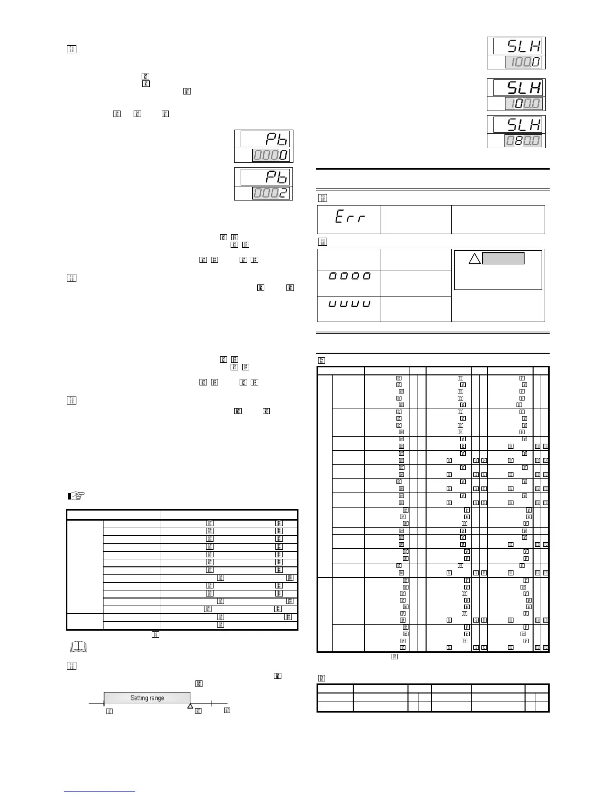
7
.
10
S
e
tti
ng
L
imit
e
r
H
i
gh
(
S
L
H
)
S
e
tti
ng
L
imit
e
r
Lo
w
(
S
LL
)
F
or voltage or current
i
nput, set scal
i
ng w
i
th
i
n the
i
nput range.
Refer to 9. IN
P
UT R
A
NG
E
T
AB
L
E
.
F
actory set value var
i
es depend
i
ng on the
i
nstrument spec
i
f
i
cat
i
on.
I
npu
t t
y
p
e
S
etti
ng
ra
ng
e *
K
0 to 1372
C
0 to 2502
F
J 0 to 1200
C
0 to 2192
F
R 0 to 1769
C
0 to 3216
F
S
0 to 1769
C
0 to 3216
F
B
0 to 1820
C
0 to 3308
F
T
C
E
0 to 1000
C
0 to 1832
F
N 0 to 1300
C
0 to 2372
F
T
199.9 to
649.0
C
* L
i
m
i
t sett
i
ng becomes
S
LH
S
LL.
When chang
i
ng the h
i
gh-l
i
m
i
t (
S
LH) and the low-l
i
m
i
t (
S
LL) l
i
m
i
ter
sett
i
ngs, always set the set-value (
SV
) w
i
th
i
n the l
i
m
i
ter range.
C
h
a
ng
e
S
etti
ng
s
E
xam
p
le
:
Th
e i
npu
t ra
ng
e (i
npu
t scale ra
ng
e) is fr
o
m 0.0 t
o
100.0
C
,
t
h
e setti
ng
limiter
h
i
gh
is 80.0
C
.
1.
P
ress the
SE
T key at “
S
LH”
i
s d
i
splayed.
2.
P
ress the sh
i
ft key to h
i
gh-l
i
ght the tens d
i
g
i
t.
3.
P
ress the
D
OWN key to change the number to 8.
4.
P
ress the
SE
T key to store the new set value.
The d
i
splay goes to the next parameter.
8
.
E
RR
O
R
D
I
SP
L
AY
S
E
rr
o
r
d
is
p
lay
R
A
M f
a
i
lure (Incorrect
set data wr
i
te, etc.)
Turn off the power at once. If an
error occurs after the power
i
s
turned on aga
i
n, please contact
R
K
C
sales off
i
ce or the agent.
Over-scale a
nd
U
nd
erscale
M
easured value (
PV
)
[
F
lash
i
ng]
PV
i
s outs
i
de of
i
nput
range.
C
heck Input type, Input range
and connect
i
ng state of
sensor.
C
onf
i
rm that the
sensor or w
i
re
i
s not broken.
[
F
lash
i
ng]
Ove

 Loading...


