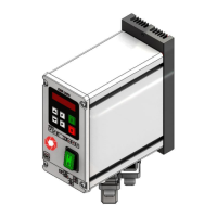
• Check whether the local mains voltage matches the device voltage (indication on the rating plate) and
whether the connection value of the feeder is within the admissible voltage range.
• Connect controller in accordance with enclosed connection diagram.
• For applications that require switching the feeder frequently on and off, you must use the enabling
input of the controller. By disconnecting the load current circuit with a contactor or a switch, the device
may be damaged.
The controllers described here have an option to adjust the resonance frequency of the connected feeder.
As in this case already a low setpoint setting may lead to full modulation of the feeder, be sure to proceed
carefully to prevent damage to the feeder due to collisions with the magnet.
However, the resonance frequency range cannot be used in practice without acceleration feedback as the
feeder would not be stable nor controllable. Therefore the operating frequency must be set at a certain dis-
tance (resonance distance) from the resonance frequency. The selected frequency can lie either above the
resonance frequency or below it.
Resonance frequencies: Based on the design of the spring-mass system of the feeders, the system can
enter resonance on several vibrating frequencies. The additional resonance points lie on a multiple of the
desired frequency. In critical cases the automatic frequency search cannot find the required vibrating fre-
quency, so that you may have to manually adjust the frequency.
As small frequency settings might lead to a an increase in the current flowing through the magnet, be sure to
check the current in the magnetic circle with an r.m.s. instrument and monitor the magnet temperature during
its first use.
Make sure that the magnets are designed for the respective operating frequency in order to avoid potential
overloading of the magnets due to excessive current input.
Since the controller output is an electronic inverter with pulse width modulated switching signals, the volt-
age and current values cannot be measured with standard measuring instruments. R.m.s. instruments, e.g.
moving-iron instruments (analog pointer-type instruments), must be used to measure these values. We rec-
ommend the use of analog instruments, seeing that electronic multimeters will not provide reliable readings
in this case.
1. Determine the vibrating frequency of the feeder.
2. Determine the max. admissible current input of the feeder
If the default setting of the controller is unknown: (See also next item ‘Notice’)
Switch on controller without connected feeder select menu item ‘C 210’, parameter FAC. (Restore factory
default setting), confirm with arrow button (SAFE) and press the P button to exit the menu. The factory default
setting is described in chapter 7 ‘Setting options’ in the table.

 Loading...