Rhein-Nadel Automation GmbH 7
VT-BA-ESR-ESM3000-EN_2021.docx / 15 March 2021
The controller is compliant with the following standards:
EC EMC Directive 2014/30/EU
EC Low Voltage Directive
2014/35/EU
Applied harmonised standards:
DIN EN 60204, part 1
EN 61439-1
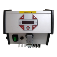
The device is operated via a control panel on the front (keys and LED display). All settings can be made via
menus displayed on this control panel. The different parameters can be accessed by entering an operator
code. In the chapter titled 'Setting Instructions' the menu function is explained in more detail. Alternatively,
the feed rate can be adjusted via an external potentiometer, an external control voltage 0...10 V, DC or a
control current 0(4).20 mA (to be selected in menu 003). A floating relay contact provides a status message
when the feeder is enabled. This contact is connected to internal terminals.
In normal operation the LED display shows the feed rate setpoint in %. In programming mode use corre-
sponding dimensions in accordance with the setting instructions. Changed settings are permanently saved
when you exit the programming mode or after 100 seconds if no button is pressed.
The controllers can generate a maximum frequency range of 5...300 Hz, which can be limited by an adjust-
able lower and upper frequency limit. The adjustable range
is maximal 1:4, i.e. the upper frequency limit can at a maximum be four times the lower frequency limit. A
limits can be set tighter to ensure that the setting does not deviate too much from the system frequency.
By an integrated current limitation, the maximum output current can be adapted to the magnet.
A special Service menu includes critical parameters like current limit and vibrating frequency range. This
menu cannot be accessed directly in the normal menu structure, but has to be enabled via an additional code
number. This is to prevent unwanted changes to these critical parameters.
With an interface option the device can be operated via a RS 232 interface or field bus systems (Profibus-
DP).
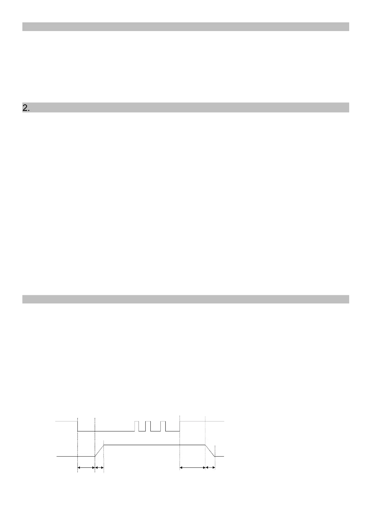
Via internal adjustable time steps („t on“ and „t off“) the output is switched ON or OFF dependent on the
material level measured by a sensor. The level of the parts to be fed swings around the position of the ma-
terial sensor installed in the filling section. The output of the controller is switched on when the level of the
parts to be fed drops below the sensor and the set ON-delay has elapsed. If the parts to be fed exceed the
position of the sensor, the output of the controller will be switched off after the OFF-delay has elapsed (dis-
play shows ‘FULL’). Any gaps in the flow of parts will reset the time steps. The times are always determined
by the last or first part to be fed. The ON- and OFF-delay times are set in the programming menu. The
elapsing of the internal time steps will be shown by flashing of the first decimal place in the display.
When the feeder is switched on, another time step 'Sensor Time-out' can be started which switches off the
feeder after an adjustable period of time (1...240 seconds) if no parts have passed the sensor during this
time. When the feeder is switched off, the status relay switches off, too. Then the display shows ‘Error’ and
‘SE’ flashing alternately. This function is optional and has to be activated in the level menu with function
‘E.En.’ = I.
 Loading...