Step
Part to remove
Description
Precfhutions
Necessary tools
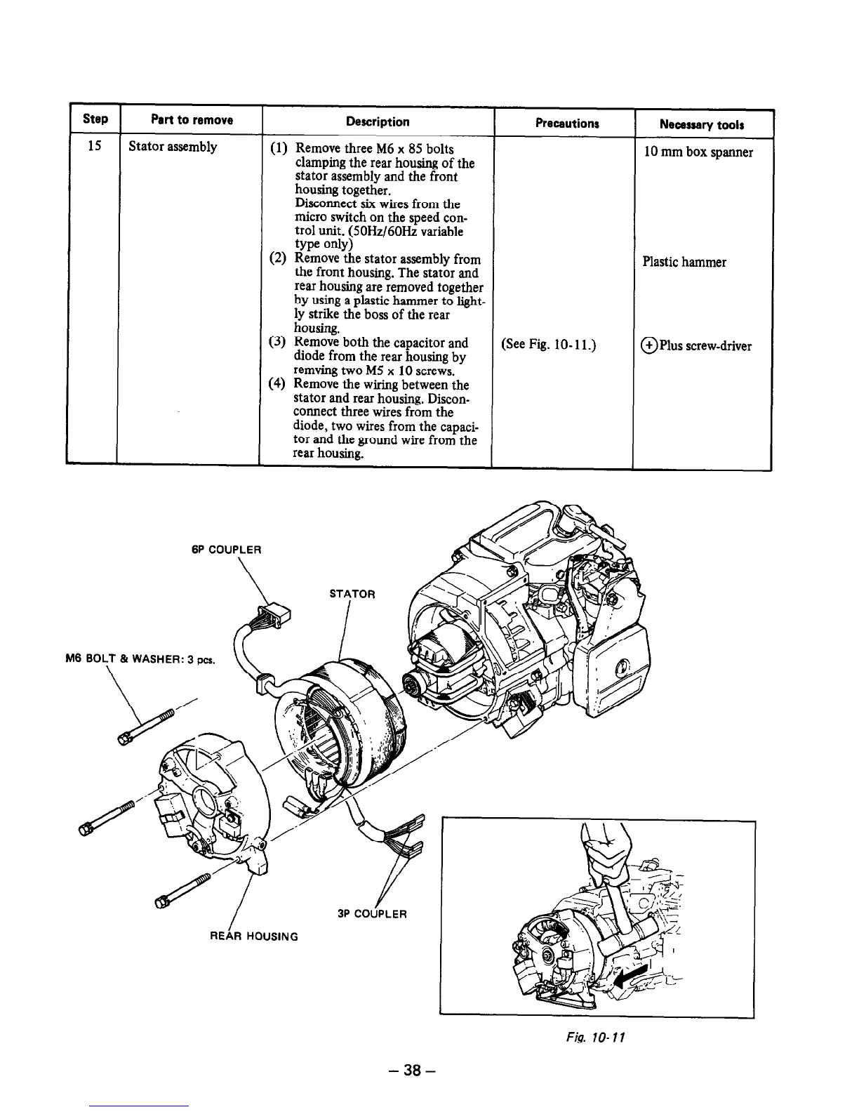
15
Stator assembly
(1) Remove three M6 x 85 bolts
clamping the rear housing of the
10 mm box spanner
stator assembly and the front
housing together.
Disconnect six wires from the
micro switch on the speed con-
trol unit. (50Hz/60Hz variable
type only)
(2) Remove the stator assembly from
the front housing. The stator and
rear housing are removed together
by using a plastic hammer to light-
ly strike the boss of the rear
housing.
Plastic hammer
(3) Remove both the capacitor and
diode from the rear housing by
remving two M5 x 10 screws.
(4) Remove the wiring between the
stator and rear housing. Discon-
connect three wires from the
diode, two wires from the capaci-
tor and the ground wire from the
rear housing.
(See Fig. lo- 11.) @Plus screw-driver
M6 BOLT & WASHER: 3
pa.
Fig. lo- 11
- 38 -
 Loading...


