9-5
ROTOR
ASSEMBLY
(1
)
Using
a
"Dr.
Robin"
Or
a
Circuit
tester, measure
the
resistance
of
the
field
coil
at
the terminals.
(Q)
MODEL
RGD5000
RESISTANCE
1.6
Q
Tble.
9-2
NOTE
7:
Because a diode is soldered to the coil ends at
the terminals, resistance may be measured only
when tester probes touche the terminals in one
combination of polarity merefore,
if
no resisfance
reading appears, try cbecking in reverse polarity.
NOTE
2
:
If the circuit tester is not sufficiently accurate, it
may not show the values given and may give er-
roneous readings. Erroneous reading will also
occur when there is a wide variation of resistance
among coil windings or when measurement is
petformed at embient temperatures dfierent from
20
"C
(68
OF).
(2)
Check
if
the surge absorber
is
burnt.
Check the resistance
of
surge adsorber.
Normal
resistance
is
-
$2
.
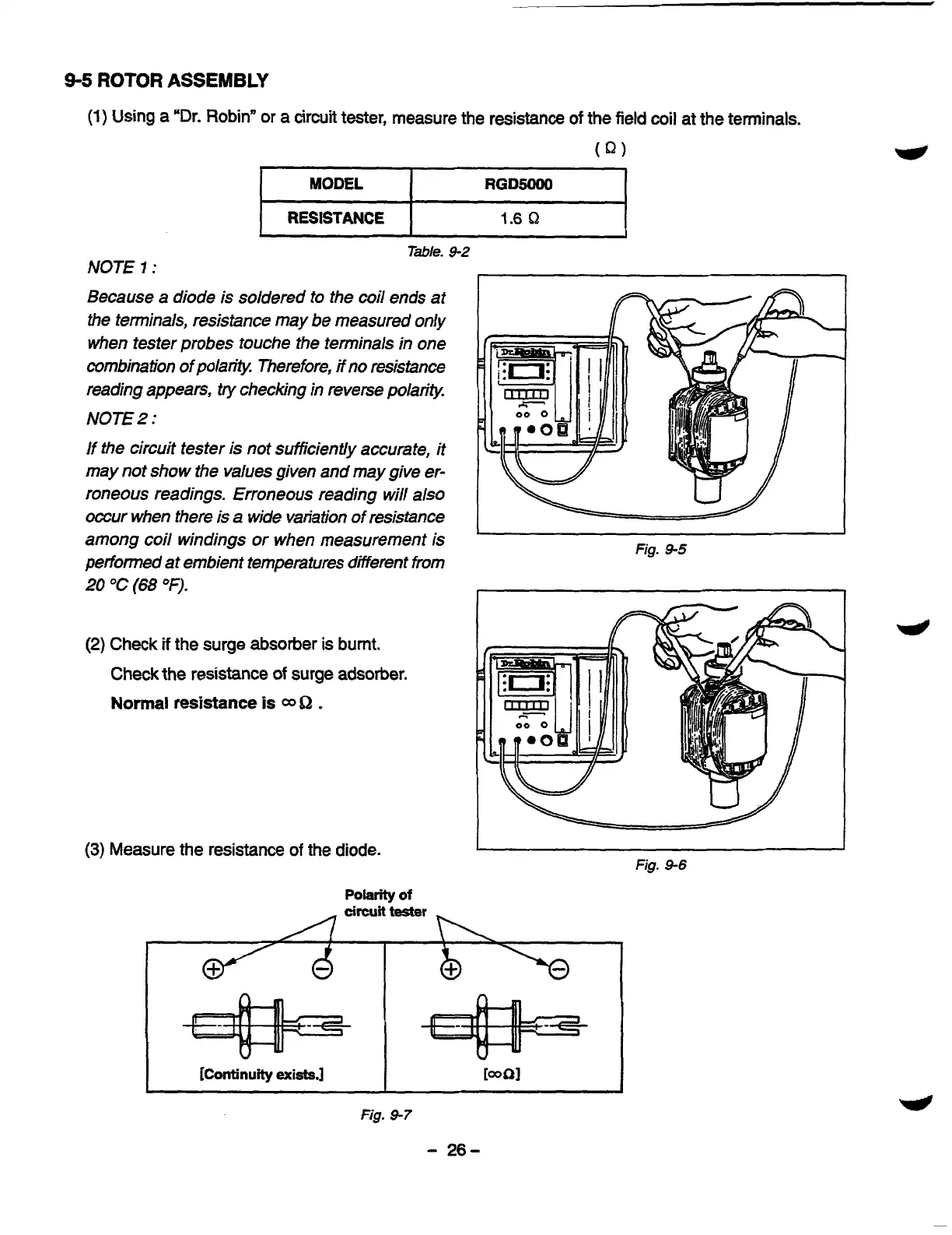
(3)
Measure the resistance
of
the diode.
Polarity
of
Fig.
9-5
Fig.
9-6
circuit
tester
[Continuity
exists.]
I
Fig.
9-7
-
26-