9.CHECKING
FUNCTIONAL
MEMBERS
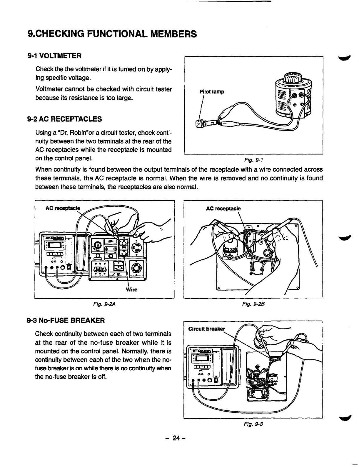
9-1
VOLTMETER
Check the the voltmeter
if
it
is turned
on
by apply-
ing specific voltage.
Voltmeter cannot be checked with circuit tester
because
its
resistance is too large.
9-2
AC
RECEPTACLES
Using
a
"Dr. Robinnor a circuit tester, check conti-
nuity between the
two
terminals at the rear of the
AC receptacles while the receptacle is mounted
on the control panel.
Fig.
9-1
When continuity
is
found between the output terminals of the receptacle with a wire connected across
these terminals, the AC receptacle is normal. When the wire is removed and no continuity is found
between these terminals, the receptacles are also normal.
I
W
I
Wire
AC
receptacle
\
Fig.
9-2A
Fig.
9-26
9-3
NO-FUSE
BREAKER
I
Circuit
breake
Check continuity between each of
two
terminals
at the rear of the no-fuse breaker while it is
mounted on the control panel. Normally, there is
continuity between each of the
two
when the no-
fuse
breaker
is
on while there is no continuity when
the no-fuse breaker
is
off.
Fig.
9-3
-
24-