10-5-2
DISASSEMBLY
(1)
Remove the control panel
from
the control box.
4
@
screw
. .
.8
pcs.
tach the control panel and box.
(2)
Disconnect the connectors on the wires to de-
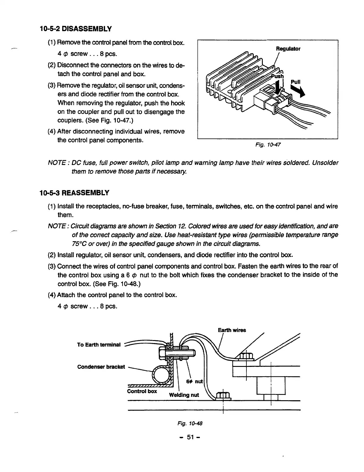
(3)
Remove the regulator,
oil
sensor unit, condens-
ers and diode rectifier from the control box.
When removing the regulator, push the hook
on the coupler and
pull
out
to disengage the
couplers. (See Fig.
10-47.)
(4)
After disconnecting individual wires, remove
the control panel components.
Regulator
1
Fig.
10-47
NOTE
:
DC
fuse,
full
power switch, pilot lamp and warning lamp have their wires soldered. Unsolder
them
to
remove those
parts
if necessity
10-5-3
REASSEMBLY
(1)
Install the receptacles, no-fuse breaker, fuse, terminals, switches, etc. on the control panel and wire
them.
NOTE
:
Circuit diagrams are shown in Section
12.
Colored
wires
are used
for
easy
identification, and are
of
the correct capacity and
size.
Use heat-resistant type wires (permissible temperature range
75°C
or over) in the specified gauge shown
in
the circuit diagrams.
(2)
Install regulator, oil sensor unit, condensers, and diode rectifier into the control
box.
(3)
Connect the wires
of
control panel components and control box. Fasten the earth wires to the rear
of
the control box using a
6
@
nut to the bolt which fixes the condenser bracket to the inside of the
control box. (See Fig.
10-48.)
(4)
Attach the control panel to the control
box.
4
@
screw.
.
.8
pcs.
To
Earth
terminal
E
Condenser
bracket
&=
I
I
Fig.
10-48
-
51
-