(2)
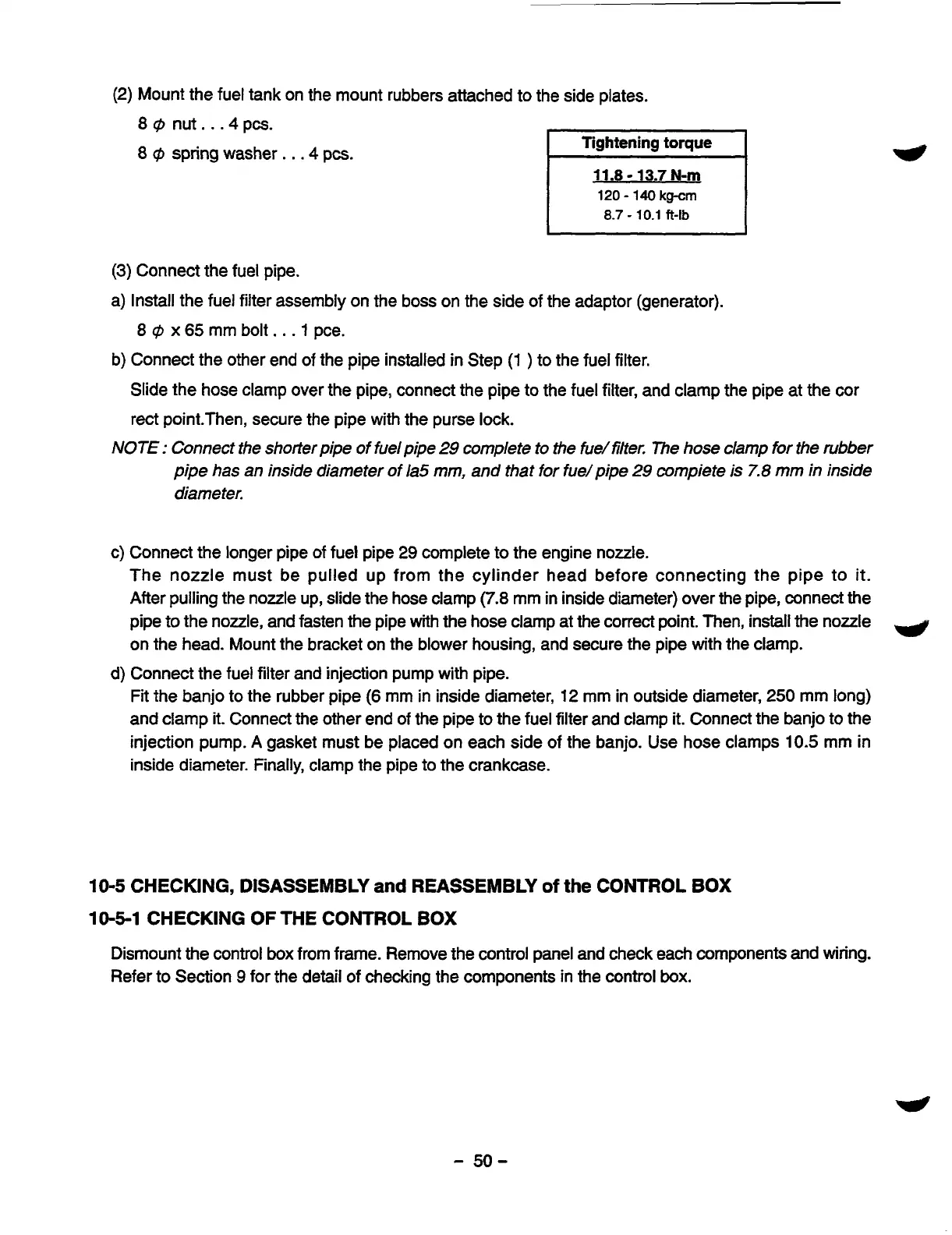
Mount the fuel tank on the mount rubbers attached to the side plates.
8
@
nut.
.
.4
pcs.
8
rp
spring washer.
.
.4
pcs.
Tightening
torque
11.8
-
13.7
N-m
120
-
140
kg-cm
8.7
-
10.1
ft-lb
(3)
Connect the fuel pipe.
a) Install the fuel filter assembly on the boss on the side of the adaptor (generator).
8
@
x
65
mm bolt.
.
.1
pce.
b) Connect the other end of the pipe installed in Step
(1
)
to the fuel filter.
Slide the hose clamp over the pipe, connect the pipe
to
the
fuel filter, and clamp
the
pipe at the cor
rect point.Then, secure the pipe with the purse lock.
NOTE
:
Connect the shorter pipe of fuel pipe
29
complete to the fud filter. The
hose
clamp for the rubber
pipe has an inside diameter of la5 mm, and that
for
fue/pipe
29
compiete is
7.8
mm
in inside
diameter.
c) Connect the longer pipe of fuel pipe
29
complete to the engine nozzle.
The nozzle must be pulled up from the cylinder head before connecting the pipe to
it.
After pulling the nozzle up, slide the hose clamp
(7.8
mm in inside diameter) over the pipe, connect the
pipe to the nozzle, and fasten the pipe
with
the hose clamp at the correct point. Then, install the nozzle
9
on the head. Mount the bracket on the blower housing, and secure the pipe with the clamp.
Fit the banjo to the rubber pipe
(6
mm in inside diameter,
12
mm in outside diameter,
250
mm long)
and clamp
it.
Connect the other end of the pipe to the fuel filter and clamp it. Connect the banjo to the
injection pump.
A
gasket must be placed on each side of the banjo. Use hose clamps
10.5
mm in
inside diameter. Finally, clamp the pipe to the crankcase.
d) Connect the fuel filter and injection pump with pipe.
10-5
CHECKING, DISASSEMBLY
and
REASSEMBLY
of
the
CONTROL
BOX
10-5-1
CHECKING
OF
THE
CONTROL
BOX
Dismount the control box from frame. Remove the control panel and check each components and wiring.
Refer to Section
9
for the detail of checking the components in the control
box.
-
50-