11-1-3
CHECKING
OF
ROTOR
(1) CHECKING FIELD COIL
Remove rem cover and startor.
Unsolder the coil from the terminal on the rotor.
(See Fig. 11
-3.)
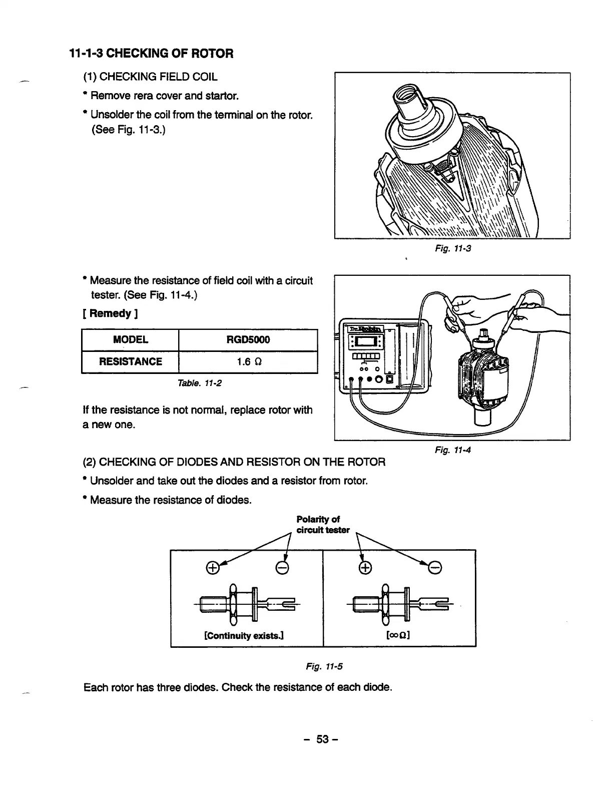
Measure the resistance of field coil with a circuit
tester. (See Fig. 11
-4.)
[
Remedy
]
I
MODEL
I
RGD5000
I
I
RESISTANCE
I
1.6
Q
I
Table.
11-2
Fig.
11-3
If the resistance is not normal, replace rotor with
a
new one.
Fig.
114
-
(2)
CHECKING OF DIODES AND RESISTOR ON THE
ROTOR
Unsolder and take
out
the diodes and a resistor from rotor.
Measure the resistance
of
diodes.
Polarity
of
I
[Continuity
existsJ
I
I
Fig.
11-5
Each rotor has three
diodes.
Check the resistance
of
each diode.
-
53-