Staging extending past an ‘A’ Frame as drawn
(see note E for ending at an ‘A’ Frame).
1. Reduce length of Staging mounting bracket,
at an ‘A’ Frame by 45mm cut opposite
end to rounded corner ‘R’.
2. Fix cleat to ‘A’ Frame
adaptor (1) with square
head bolt and then insert the
assembly inside the ‘A’ Frame (as shown
Fig. 2) to your required height. Check bracket
for height and level again, then drill a 7mm
(
1
/4”) diameter hole ‘H’ through ‘A’ Frame
and adaptor and secure with item 2.
3. Fix mounting bracket to cleat (square head
bolt).
4. Fit bottom of Tubular Brace to adaptor (1) and
the top to mounting bracket (square head bolt)
inserting adaptor inside the ‘A’ Frame. Adjust
adaptor position until mounting bracket is level
and then drill a 7mm (
1
/4”) diameter hole ‘H’
through ‘A’ Frame and adaptor and secure
with item 2.
5. If Staging ends at an ‘A’ Frame use end
mounting cleat (4 or 5 on main instructions)
with left or right hand mounting bracket
positioned with “flange up” to close end of
Staging.
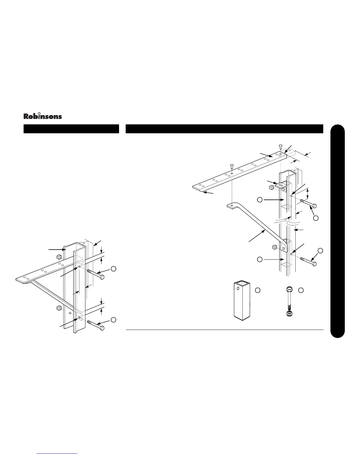
When Shelving extends past or ends at an ‘A’
Frame reinforcing channel.
Fix top slope bracket to horizontal bracket with
square head bolts and insert the assembly fully
inside the ‘A’ Frame to your required height.
Check for level and then drill two 7mm (
1
/4”)
diameter holes “H” (as shown Fig. 1).
Check again for height and level prior to
tightening the bolts to clamp the brackets in
position.
It may be necessary to lightly file the edge of
brackets for ease of fitting inside ‘A’ Frame.
‘A’ Frame Adaptor Assembly Instructions
StagingShelving
Fig. 2
Tubular
Brace
Fig. 1
1
1
1
2
2
‘H’
‘H’
‘A’ Frame
‘R’
Mounting
Cleat
Mounting
Bracket
Cut
25mm
30mm
45mm
2
‘A’ Frame
adaptor
(Staging)
M6 x 35mm
Bolt and Nut
2
2
‘H’
‘H’
‘A’ Frame
Glazing
Bar
15mm
10mm
10mm
27
‘A’ FRAME INSTRUCTION