8
Glazing the Sides
41. Identify the slam rail (from vent kit) and slide the brush
strip along its length, protruding each end by
approximately 5mm. Then using standard M6 X 10
bolts and nuts attach the fixing cleats (No. 22, ID
Chart). Next identify 2 cropped head bolts (No. 24, ID
Chart) and ensuring that they are located into the
glazing bars on either side of the vent, slide rail down
onto edge of glass, tighten nuts to secure.
NOTE: See separate instruction leaflet
in opener box for full details.
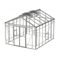
GLAZING THE SIDES
43. With reference to the glazing plan identify glass, PVC
corner bar capping, PVC standard bar capping (No.
14 and 15 ID Chart), 4mm separator strips for glass
(No 25 ID Chart).
44.Bar capping will be almost the same length as side
glazing bars.
45. Starting from one corner, position first 610 x 305 panel
fitted with 4mm separator strip.
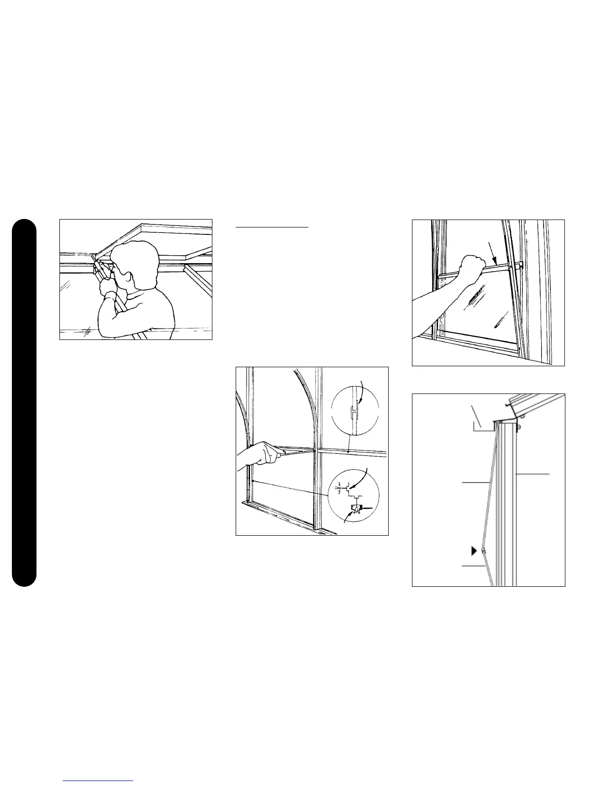
46. Select corner bar capping and secure with bottom self
tapping screws (No.17, ID Chart) only at this stage.
47.Continue fitting the 610 x 305 panels using standard
bar capping, finishing the row with another bar
capping.
48.Fit the next sheet of glass into the 4mm separator.
49.Follow drawing to position glass under gutter.
4mm separator
4mm separator
Gutter member
PUSH
Glazing bar
Bottom row of glass
Top row of glass
Outside
Corner bar
Corner bar capping
Inside