Features and technical data
Installation, use and maintenance manual – Next-R
15
1
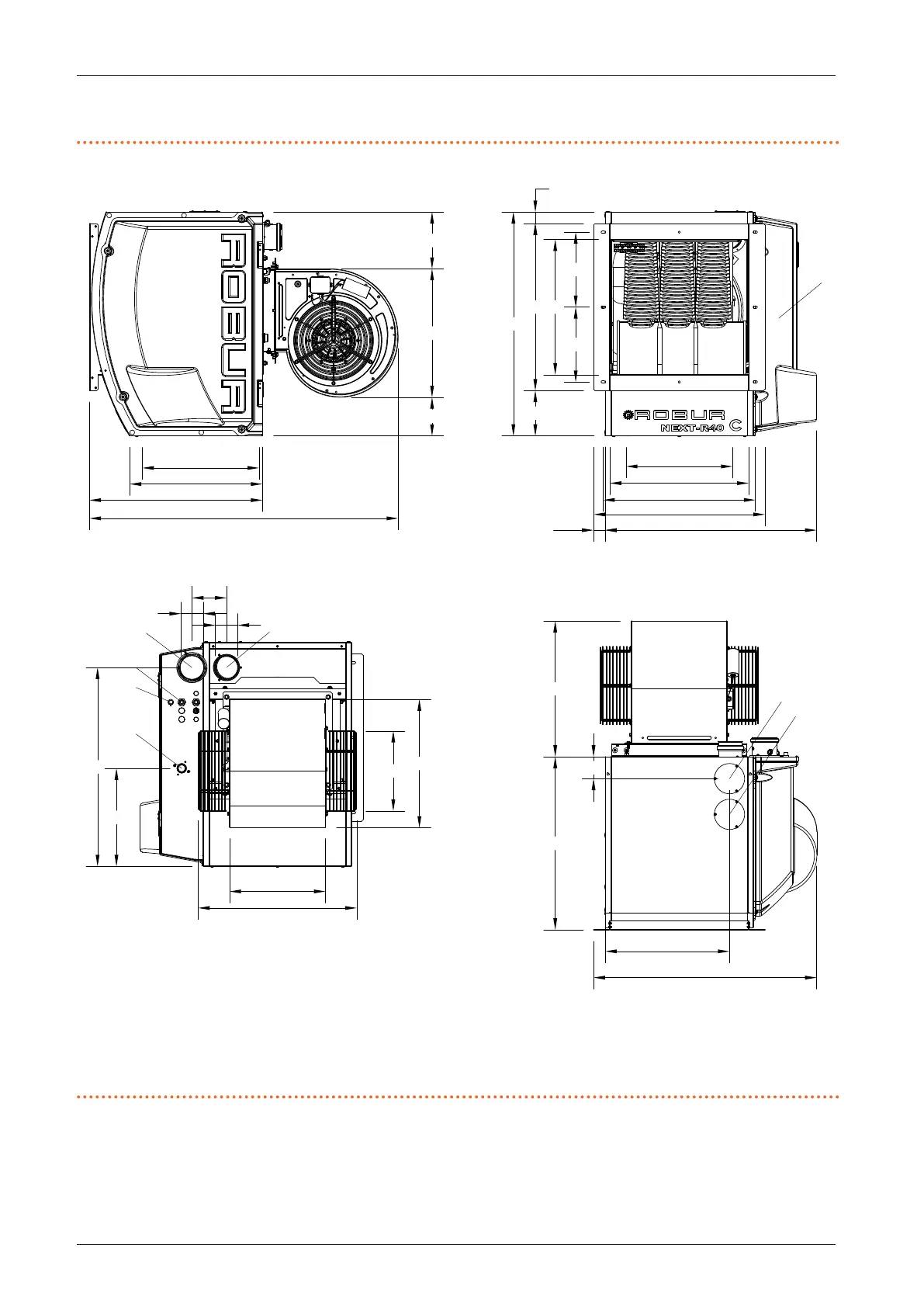
1.2.2.2 R40 C
Figure1.8 Unit dimensions
1 Flue gas exhaust
2 Combustion air inlet
3 Power supply cables input
4 Gas connection 3/4" M
5 Thermoformed door
6 Limit thermostat
7 Flue gas exhaust blind cover, alternative to the rear one (1)
8 Blind cover for access to the fan thermostat
(*) Holes for xing to the support bracket
734
777
774
601
472
157
580
469
260
260
40
595
528
482
1072
601
460
134
446
197
80
80
12
3
4
6
690
340
446
333
550
278
405 (*)
370 (*)
120
7
8
76
432


 To Next Page