First start-up
Installation, use and maintenance manual – Next-R
43
5
4. Screw in completely the throttle adjustment screw (D).
5. Screw in completely the oset adjustment screw (C).
6. Unscrew the throttle adjustment screw (D) as indicat-
ed in the following Tables, depending on the model
and the gas type used.
7. Unscrew the oset adjustment screw (C) as indicated
in the following Tables, depending on the model and
the gas type used.
8. Open contact 27 (L-C terminals), or act on the power
level control device to force gas unit heater operation
at minimum power.
9. Switch on the gas unit heater using the provided con-
trol device.
10. After about 2 minutes from the burner ignition, the
combustion control at minimum power can be carried
out.
11. Ensure the CO
2
value is between values indicated in
column "Minimal heat input" of the following Tables,
depending on the model and the gas type used.
Otherwise set CO
2
percentage reading by acting on
the oset adjustment screw.
Check the burner, which must not have reddened
areas.
12. Close contact 27 (L-C terminals), or act on the power
level control device to force gas unit heater operation
at maximum power.
13. Ensure the CO
2
value is between values indicated in
column "Nominal heat input" of the following Tables,
depending on the model and the gas type used.
If the check is successful:
14. Set contact 27 (L-C terminals) back in its original posi-
tion or stop manual forcing of the power level.
15. Screw the cap back over the oset adjustment screw
(C) of the gas valve.
16. Close the thermoformed door.
If the check is not successful:
17. Repeat steps 8 to 10 to reactivate the minimum power
operation; verify once again and, if necessary, correct
the CO
2
value in these conditions by actuating the o-
set adjustment screw.
18. Repeat steps 12 and 13 to reactivate the maximum
power operation; verify once again and, if necessary,
correct the CO
2
value in these conditions by actuating
the throttle adjustment screw.
19. Repeat steps 14 to 16 to complete the procedure.
Check that the static and dynamic supply gas
pressure values, with the gas unit heater running
at maximum power, correspond to what is shown
in Table 3.1
p. 29
(with low supply gas pressure
values the CO
2
value will also be at minimum
values).
If the control systems are designed so that the
gas unit heater activation request depends on the
room temperature, the gas unit heater may not
start because the room temperature is already at
requested setpoint. In this case, set the forcing for
manual activation on the control system, or close
contact Z9 (Z91-Z92 terminals) manually.
Remember to set contact 27 (L-C terminals) back
in its original position or stop manual forcing of
the power level after the conclusion of checking
operations.
If it has been set, remember to disable the
forcing for manual activation on the control
system, or manual close of contact Z9 (Z91-Z92
terminals).
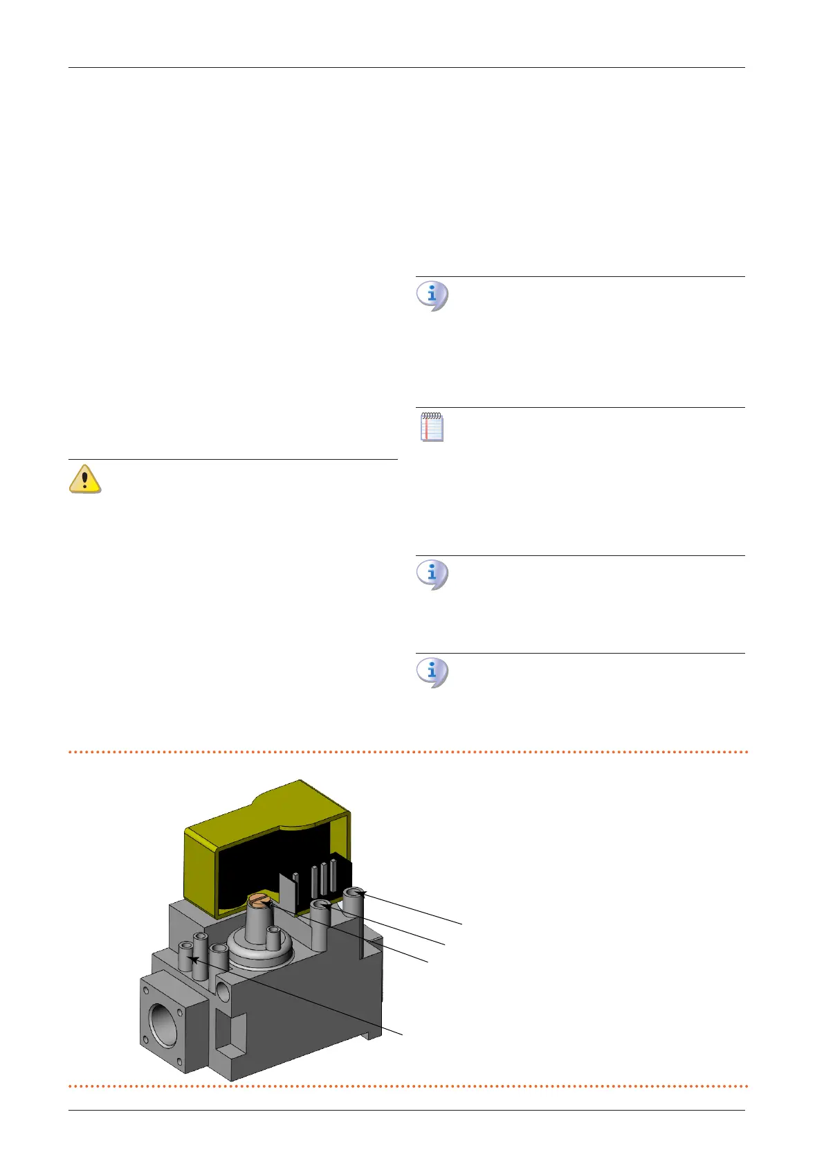
Figure5.1 Gas valve
A Oset pressure intake
B Gas mains pressure intake
C Oset adjustment screw
D Throttle adjustment screw
A
C
D