226 Rockwell Automation Publication 1766-UM001O-EN-P - September 2021
Appendix F MicroLogix 1400 Distributed Network Protocol
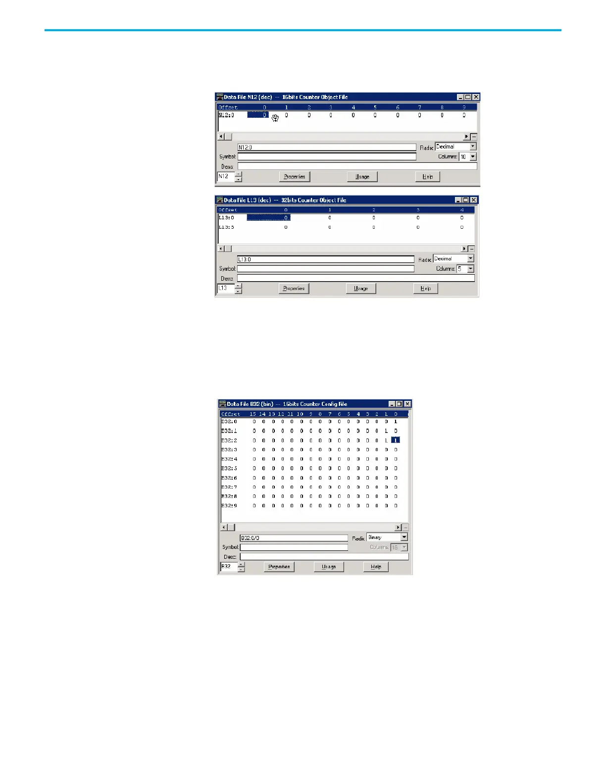
Let's suppose you configured both 16-bit and 32-bit Counter Object Files as
below. Data File N12 has 10 elements and L13 has 10 elements accordingly. In
total, 20 Counter Object indexes are configured. Index 0 of the Counter Object
is N12:0, Index 1 is N12:1, Index 10 is L13:0, and Index 19 is L13:9.
As an example, a Counter Config File is shown below. These files have 10
elements for each. B32:0/0 and B32:0/1 can be configured for Class Level 0, 1, 2,
or 3 for DNP3 Index 0 of the 16 bits Counter Object File. B32:1/0 and B32:1/1 can
be configured for Class Level for DNP3 Index 1 of the Counter Object File.
Default Class Level is 0. Any other bits are reserved. So, in the example below,
for 16-bit Counter Config File, Class Level of Index 0 is 1(B32:0/0 and B32:0/1),
Class Level of Index 1 is 2(B32:1/0 and B32:1/1), Class Level of Index 2 is 3(B32:2/
0 and B32:2/1), and Class Level of other Indexes are 0.
 Loading...


