Rockwell Automation Publication 1766-UM001O-EN-P - September 2021 51
Chapter 3 Wire Your Controller
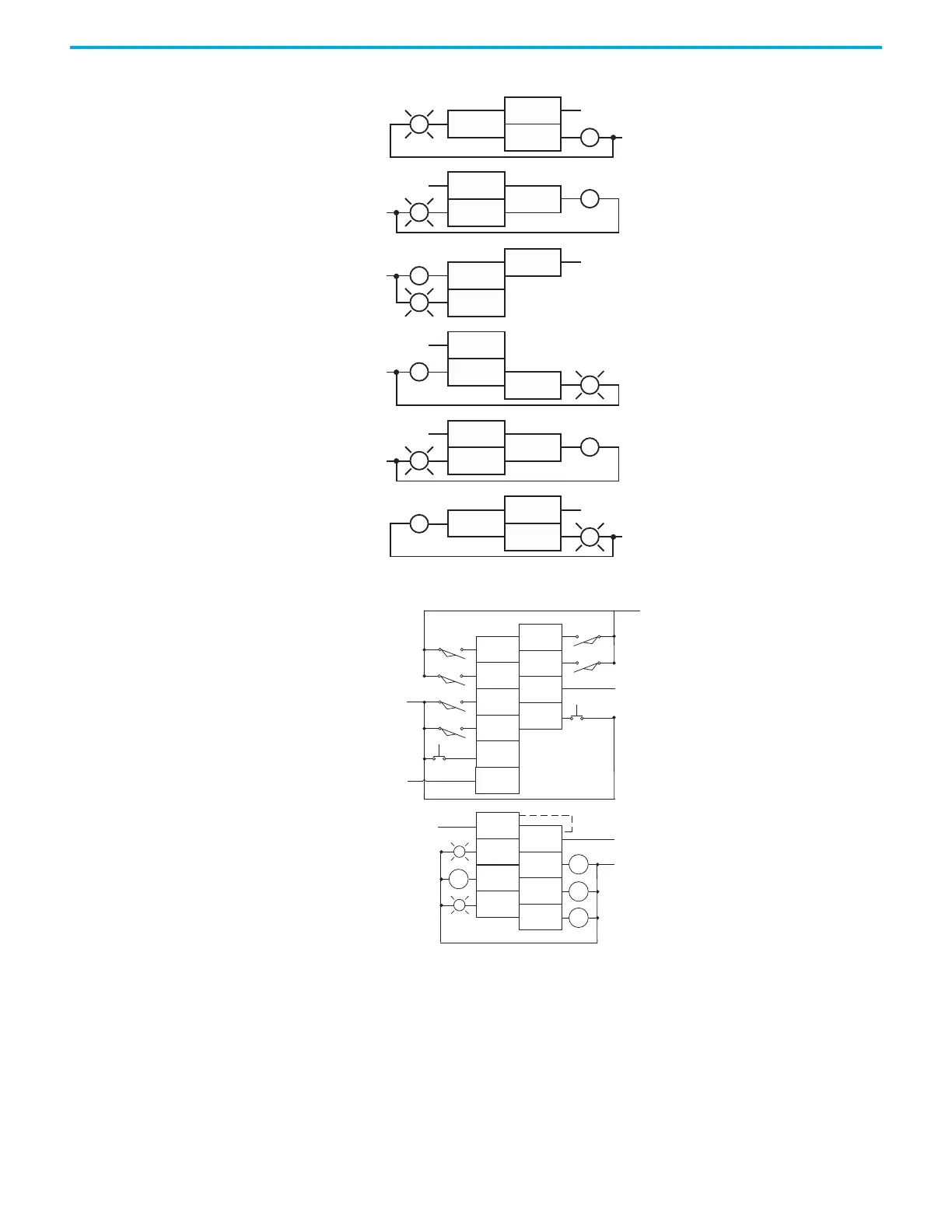
Figure 33 - 1762-OX6I Wiring Diagram
Figure 34 - 1762-IQ8OW6 Wiring Diagram
Analog Wiring
Consider the following when wiring your analog modules:
• The analog common (COM) is not connected to earth ground inside the
module. All terminals are electrically isolated from the system.
• Channels are not isolated from each other.
• Use Belden 8761, or equivalent, shielded wire.
L1-0
L1-1
L1-2
L1-3
L1-4
L1-5
OUT0 N.C.
OUT0 N.O.
OUT1 N.C.
OUT1 N.O.
OUT2 N.C.
OUT2 N.O.
OUT3 N.O.
OUT3 N.C.
OUT4 N.C.
OUT4 N.O.
OUT5 N.C.
OUT5 N.O.
CR
CR
CR
CR
CR
CR
L1 OR +DC
L1 OR +DC
L1 OR +DC
L1 OR +DC
L1 OR +DC
L1 OR +DC
L2 OR -DC
L2 OR -DC
L2 OR -DC
L2 OR -DC
L2 OR -DC
L2 OR -DC
IN 6
IN 4
IN 3
IN 1
IN 5
IN 2
IN 0
OUT 4
OUT 2
OUT 0
VAC
VDC
VAC
VDC
DC
COM 1
OUT 3
OUT 1
IN 7
L1 or +DC
L1 or +DC
-DC (sinking)
+DC (sourcing)
Connected internally
+DC (sinking)
-DC (sourcing)
L2 or -DC
OUT 5
+DC (sinking)
-DC (sourcing)
-DC (sinking)
+DC (sourcing)
DC
COM 0
CR
CR
CR
CR
 Loading...


